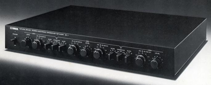
YAMAHA EC-1
¥ 280,000 (around 1979)
Commentary
Electronic crossover network with continuously variable crossover frequency, 3-stage slope selector, and Q control circuit.
The EC-1 consists of an input buffer amplifier based on Yamaha's original DC-amplifier module, a low-pass filter for low band, a high-pass filter + low-pass filter for middle band, and a Route 3 filter unit for high-pass filter for high band, connected in parallel with a time-constant device that employs a high-speed, wide-band, highly reliable operational amplifier and high-precision resistors and capacitors.
Each filter can vary the crossover frequency by five octaves continuously, and the slope characteristics can be changed between 6dB/oct., 12dB/oct., and 18dB/oct. When the slope characteristics are 12dB/oct., Q, which represents the filter's shoulder characteristics, can be controlled in the range of 0.5 to 1.
The Dividing Function Selector on the rear panel allows you to select three filter modes : 3-way, 2-way-1 and 2-way-2.
The circuit configuration of the buffer amplifier consists of Yamaha's original low-noise dual-FET differential-amplifier circuit, cascode bootstrap, first stage of current mirror circuit assembly, base-grounded amplifier drive stage, and pure complimentary service push-pull emitter-follower complimentary service stage with high fT and uniform output characteristics.
This buffer amplifier uses a low-noise Dual FET at the first stage to reduce noise. The cascode bootstrap circuit and current mirror circuit are assembled to prevent the mirror effect due to the FET feedback capacitance to improve frequency characteristics. In addition, problems such as degradation of distortion due to variation of signal source impedance and drift of mid-point voltage of DC amplifier are solved by the adoption of cascode bootstrap circuit and Dual FET to obtain excellent low-distortion characteristics and stability.
The second stage common-base amplifier circuit can minimize the mirror effect compared with common-emitter amplifier circuit, etc., and is stable against a large amount of NF in a wide band.
The pure complimentary service push-pull emitter-follower at the final stage is equipped with complimentary service transistors with sufficient Pc margin and high fT pair characteristics, so that three pairs of parallel-connected filter circuits can be driven with sufficient A-class margin.
In addition, this buffer amplifier is packaged in a plastic case and hardened with epoxy resin to form a module, and reliability and temperature characteristics are improved.
The EC-1 uses 16 sets of filter amplifiers, 2 sets each for each filter. The filter amplifier uses a voltage follower circuit based on the High-Speed wide-band operational amplifier ICLM 310, which realizes sufficient attenuation characteristics by obtaining sufficient output impedance of 1 Ω or less.
The voltage follower ICLM 310 is an IC equivalent to 19 transistors and is a DC amplifier configuration with a cascode bootstrap circuit. It realizes high-speed, wide-band, and high reliability with low noise.
The filter circuit has three types of slope characteristics : 6dB/oct., 12dB/oct., and 18dB/oct.
The 6dB/oct filter is a passive filter with an output buffer amplifier. The crossover frequency can be changed every one octave by switching C and continuously within ± 0.5 octave by VR.
The 12-dB / oct. filter is a second order active filter. The crossover frequency can be changed by one octave by switching two sets of C switches, and can be continuously changed within ± 0.5 octave by two linked VRs. It is also equipped with a Q control circuit that can subtly control shoulder characteristics near the crossover frequency.
The 18dB/oct. filter has a CR-1 stage passive filter with an output buffer after a 12dB/oct., Q = 1 secondary active filter to obtain the flattest characteristics. The crossover frequency can be changed by one octave by switching three sets of C, and can be continuously changed within ± 0.5 octave by three linked VRs.
The sound quality and characteristics are improved by using carefully selected parts.
We have adopted Yamaha's original low-noise Dual FET (2SK100) for the first stage of the buffer amplifier. We have also adopted low-noise signal amplifiers with particularly good linearity. We have also adopted a high-speed, wide-band, high-reliability voltage follower ICLM 310 for the filter amplifier.
All of the capacitors used in the signal system as the time constant element of the filter are high-precision ± 1% polypropylene film capacitors. These polypropylene film capacitors not only have high accuracy, but also have low tan δ and excellent high-frequency characteristics, and excellent results are obtained even in a hearing check.
A metal film resistor with a structure in which a resistor and an electrode are formed on a ceramic substrate by vacuum evaporation method and then covered with an epoxy resin is used. This metal film resistor has excellent characteristics such as a temperature coefficient of ± 50 ppm / ℃ and an error of ± 1%.
All variable resistors are made of conductive plastic volume, which is highly accurate within ± 2% accuracy and within ± 1 db of gang error.
A double-sided through hole glass epoxy substrate is used for the substrate. In addition, low-distortion switches are used with attention paid to the distortion generated by the switches in use. All input / output terminals are gold-plated.
The Dividing Function selector allows you to select three filter modes : 3-way, 2-way-1, and 2-way-2, and Pass mode.
The 3-way position operates as a Low, Mid, and High 3-way network with two crossover point LEDs lit. The 2-way-1 position operates as a 2-way network with a crossover point between Low and Mid, and the 2-way-2 position operates as a 2-way network with a crossover point between Mid and High.
The Pass position operates as a 0 dB gain full-range buffer amplifier, and is output to the Low terminal on the rear panel.
The Slopep selector allows you to select slope characteristics of 6dB/oct., 12dB/oct., and 18dB/oct. independently at four points (LPF side and HPF side) at the upper and lower crossover points.
The 6dB/oct position has a gentle cutoff characteristic, so that smooth sound connection can be obtained when the characteristics of the speaker unit used are wider and better than the frequency band set by Crossover.
At the position of 12dB/oct., Q, which represents the shoulder characteristics of the filter, can be controlled from 0.5 to 1.
A position of 18dB/oct is effective when the crossover frequency is close to the divided vibration region of the unit because the cutoff characteristic is steep.
The crossover selector allows you to select five points of 50Hz/100Hz/200Hz/400Hz/800Hz per octave between Low and Mid, and five points of 800Hz/1.6kHz/3.2kHz/6.4kHz/12.8 kHz per octave between Mid and High.
In addition, the frequency set by the crossover selector can be adjusted continuously by ± 0.5 octave on the LPF side and HPF side independently by the crossover fine adjustment knob. Therefore, the crossover frequency can be adjusted continuously from 35 Hz to 1.13 kHz between Low and Mid and from 565 Hz to 18.1 kHz between Mid and High.
With the Q control, when the slope characteristic is 12dB/oct., Q, which represents the shoulder characteristic of the filter, can be continuously adjusted in the range of 0.5 to 1. This allows you to adjust the sum of the outputs of the crossover band to compensate for peaks and dips in the crossover band.
Ten memory cards are included to record the settings of the various controls of the EC-1. These memory cards can be stored in the memory card holder at the bottom of the EC-1.
High Quality Gold Plated Three Pin-Pin codes are included. This Pin-Pin code is equivalent to the commercial product CP-10 (¥ 2500) and has double spiral structure with DC resistance of 0.07 Ω (reciprocating) and capacitance of 120 pf (1 khz, 1.2m).
.JPG)
.JPG)
.JPG)
.JPG)
.JPG)
.JPG)
.JPG)
.JPG)
.JPG)
.JPG)
Model Rating
| Type | Electronic crossover network |
| Configuration | Input : Dual FET cascode bootstrap buffer amplifier Filter : High-speed and wide-band operational amplifier |
| Channel separation | 70 dB (1 kHz, 10 dBm input) |
| Crossover frequency | On normal selection Low-Mid : 50 Hz, 100 Hz, 200 Hz, 400 Hz, 800 Hz Mid-High : 800 Hz, 1.6 kHz, 3.2 kHz, 6.4 kHz, 12.8 kHz By the crossover fine adjustment knob Low-Mid : 35 Hz to 1.13 kHz continuously variable Mid-High : 565 Hz to 18.1 kHz, continuously variable |
| Cutoff characteristic | -6dB/oct., -12dB/oct., -18dB/oct. |
| Q-control characteristic | -12dB/oct. : 0.5 to 1.0 continuously variable |
| Damping property | -85dB or more |
| Rated Input / Impedance | 1V/50k Ω |
| Rated Output / Impedance | 1V/300 Ω |
| Allowable Input / Maximum Output | 7V/7V (THD 0.01%, 1 kHz) |
| Frequency characteristic | 10 Hz 0 ± 0 dB (Low Range or Pass Position) 100 kHz 0 ± 0 dB (Low Range or Pass Position) DC ~ 100 kHz 0 + 0 -0.5 dB (3/2way sum characteristic or pass position) |
| Insertion loss | 0dB |
| Harmonic distortion factor (20 Hz to 20 kHz) | 0.003% (at rated output) 0.01% (at 4 V output) |
| Signal-to-noise ratio (IHF-A network) | 102 dB (at rated output) |
| Pwer | 100 VAC, 50Hz/60Hz |
| Rated power consumption | 15W |
| External dimensions | Width 435x Height 72x Depth 349 mm |
| Weight | 7.5kg |
| Attachment | 3 Pin-Pin x3 10 memory cards |