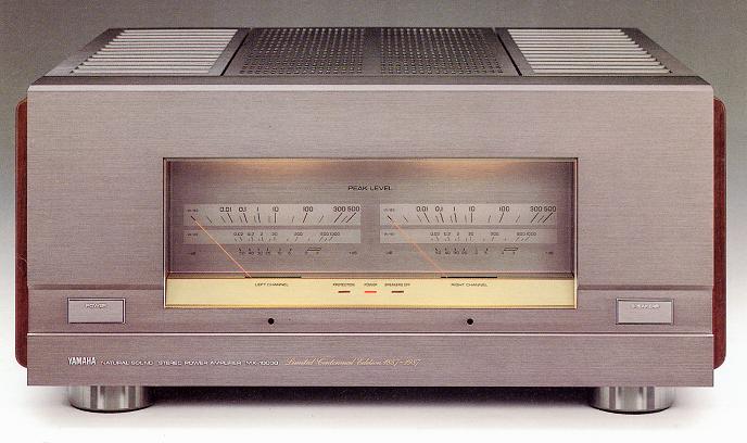
YAMAHA MX-10000
¥ 800,000 (released in 1987)
Commentary
A power amplifier developed by Yamaha to commemorate the 100th anniversary of its founding.
An HC (hyperbolic transformation) class A operation circuit is adopted in order to solve the weak point of class A operation circuit, which shifts to class AB operation during low impedance driving.
This hyperbolic conversion uses the characteristics of the collector current and base-emitter voltage of the transistor and consists of two dual transistors. Thus, even if the current exceeds twice the idling current, class A operation is maintained and linearity of input / output is maintained.
However, since the HC circuit has no gain, a power MOS FET and power current mirror output circuit are provided in the latter stage.
The output device is a 4-para push-pull power MOS FET with high-speed and high-current operation developed for the MX-10000.
In addition, in order to solve the large-scale heat generation problem of class A amplifier, a dual amplifier class A configuration using two SEPP amplifiers in one channel is adopted. In addition to the output stage for current amplification, a power buffer amplifier for supplying necessary power is mounted.
The power buffer contains Hi-f of Pc 200W, which boasts high performance as an output device for audio.TIt uses a power transistor and consists of 6 para push-pull.
In the dual amplifier Class A, since the ground is a non-current ground that only determines the ground potential, unstable elements of the amplifier due to current flowing in the ground are also eliminated.
The voltage amplifier for voltage amplification employs a class A operation circuit for all stages : dual FET differential input for the first stage, current mirror for the second stage, and emitter follower push-pull for the last stage.
The dual-FET differential input and current mirror enable low-distortion signal amplification with little loss. The emitter-follower push-pull enables low-impedance signal output. In addition, the voltage amplifier incorporates a floating power supply circuit, and the voltage corresponding to the amplitude of the input signal is fed to the first and second stages. Therefore, even if there is a transient input, the amplifier can be used with a margin without saturation. Thus, highly stable voltage amplification is obtained.
The power supply section includes a power MOS FET output stage equipped with an HC circuit, and Hi-f to eliminate mutual interference of signal systems fluctuated by large amplitude signals.TEach power supply to a power buffer that employs a power transistor uses an ICP system with independent current loops.
The power supply section is independent of the transformer. The power supply for the output stage and the + B and -B power supplies for the power buffer are independent from the transformer winding to the power supply circuit to form the current loop for the output stage and the power buffer respectively, thereby stabilizing the operation state of the transformer.
The output current is supplied from the + B power supply and -B power supply, and the output stage power supply is independent of the output current. Therefore, the power supply does not fluctuate even at large output, and the class A operation is supported from the power supply side.
In order to avoid the deterioration of sound quality caused by the interposition of speaker selector switch, only one stereo system is used as the speaker output.
In addition, by using only one system, the NFB loop is extended to the output terminal of the speaker with high stability, and the terminal from the power MOS FET output stage and the Hi-fTIt is equipped with a direct error collection amplifier that directly feeds back the signal from both terminals of the terminal from the power transistor and power buffer to correct distortion. It eliminates not only the slight distortion generated at the output stage but also the minute non-linear of the output coil and speaker relay.
Aiming to obtain high strength construction and electrical and mechanical ground potential, it is symmetrical construction on both sides, and high rigidity non-magnetic aluminum extruded material is used entirely for chassis / frame.
The front panel is 12 mm thick, the main chassis and frame is 5 mm thick, and the rear panel is 3 mm thick. The thickness of each member is changed in stages. Each member is firmly fixed with screws. It has characteristics unique to extruded materials that do not cause metal fatigue such as bending descent. Furthermore, acoustic tuning is applied taking into consideration the continuity of the strength distribution of each structural material. Thus, the chassis / frame has a high balance of organic structure that combines beauty and beauty.
A large 3-piece heat sink is used to dissipate heat from the 20 output elements used in the power stage.
The heat-radiating fins have a resonance dispersion type structure in which the length of each fin has a gradation structure with different base thicknesses, thereby dispersing the vibration mode peculiar to the heat sinker and eliminating the generation of modulation noise caused by squeal.
In addition, on the mounting side, a cork-spacer is inserted in the part where the heat radiation fin touches, and it is mounted rigidly on a high-rigidity chassis, and the heat sinker is part of the structure to prevent the occurrence of unnecessary resonance.
The 6-mm-diameter brass and gold-plated shaft connects the power stage amplifier circuit board and power supply circuit board to each other through a heat sinker, thereby eliminating the possibility of subtle errors in wiring processing and changes in characteristics caused by such errors.
In addition, OFC (oxygen-free copper) gold-plated bus bars are embedded in the power stage amplifier substrate, and a rigid method in which current flows through low impedance is adopted.
All electrical connections from the input to the output are gold-plated, including screws and washers.
The power transformer employs a toroidal type with low leakage flux, and is equipped with a large double toroidal transformer with a total weight of 15 kg. The transformer consists of two layers of two toroidal transformers for output stage and power buffer.
The inside of the shield case is filled with a filler to suppress the noise of the transformer.
In addition, taking advantage of the advantages of a toroidal power transformer with excellent coupling between the primary and secondary sides, a toroidal choke is separately inserted in the primary side to improve the rectification characteristics as a semi-choke input rectification. This prevents sudden fluctuations in AC voltage caused by the rush current when the power is turned on, and prevents mutual power interference between audio component devices during normal operation.
The Chemi-Con for smoothing uses constant magnification foil and high-quality audio aluminum electrolytic capacitors with excellent temperature stability and low current ripple.
The power MOS FET output stage has a capacity of 100,000 μ Fx2 and the power buffer amplifier has a capacity of 22000 μ Fx4, for a total capacity of 288000 μ F. It is also located in the center of the power amplifier for construction purposes, and a well-balanced power supply to the amplifiers of both LR channels.
A protection circuit is provided to prevent damage to the output elements and speakers due to short-circuit accidents.
The protection system eliminates the PC limiter, which tends to cause sound quality degradation for low impedance loads and capacitive loads, and uses a protection circuit system with a relay switch that cuts off output only when overcurrent or DC component is detected.
In addition to the power switch, a protection linked speaker switch is provided.
This allows you to turn the speaker output on and off while the output is in standby mode.
It is equipped with a dB scale logarithmic compression type peak level meter independent of LR to indicate the output power level to the speakers.
Instantaneous output wattage can be read at load levels of 8 Ω and 4 Ω.
The parts used use high-grade elements that have been carefully examined for sound quality.
We use polypropylene film capacitors and mica capacitors as in-circuit capacitors, metal-coated resistors and non-inductive wound resistors with copper leads as resistors, and hollow-dip OFC coils as output coils.
The input terminal uses a gold-plated brass machined pin jack with excellent corrosion resistance and contact properties.
The speaker output terminal uses a large, gold-plated screw type that is suitable for extremely thick cables.
The AC power cord uses a 10 mm diameter cable made of OFC wire, and polarity is indicated on the plug.
There is a dedicated cable connection terminal (transmit / receive) that enables the MX-10000 to be turned on / off in conjunction with the CX-10000 power on / off.
By providing transmission terminals in addition to receiving terminals, power ON / OFF relay between MX-10000 in DSP systems is also possible.
A photocoupler is used to transmit the power control signal to prevent degradation of sound quality.
.JPG)
.JPG)
Model Rating
| Type | Power amplifier |
| Rated Output (20 Hz ~ 20 kHz) | 8 Ω load : 250W + 250W (0.001% THD) 6 Ω load : 300W + 300W (0.001% THD) 4 Ω Load : 400W + 400W (0.002% THD) |
| Dynamic Power (1 kHz) | 8 Ω load : 350W + 350W 6 Ω load : 450W + 450W 4 Ω load : 600W + 600W 2 Ω load : 900W + 900W 1 Ω load : 1200W + 1200W |
| Damping factor | 1000 (1 kHz, 6 Ω) |
| Input Sensitivity / Impedance | 1.5V/25k Ω |
| Frequency characteristic | 2 Hz ~ 300000 Hz + 0 dB -2dB |
| Total harmonic distortion factor | 0.0005% (20 Hz to 20 kHz, 150W/ch, 6 Ω) |
| Signal-to-noise ratio | 132 dB (IHF-A corrected) |
| Residual noise | 10 μ V (IHF-A correction) |
| Channel separation | 90 dB (20 Hz to 20 kHz) |
| Pwer | AC100V 50/60Hz |
| Power consumption | 600W |
| External dimensions | Width 475x Height 220x Depth 543 mm |
| Weight | 43kg |