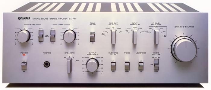
YAMAHA CA-R11
¥ 73,800 (around 1978)
Commentary
A pre-main amplifier developed based on CA-R1 and incorporating CA-S1 technology.
The basic circuit configuration consists of three circuits : a DC equalizer with a low-noise dual FET at the first stage, a DC flat amplifier, and a DC main amplifier with a High Speed High ft transistor equipped with an Ro control that can continuously change the output impedance of the amplifier from -1 Ω to + 1 Ω. In addition, a low-noise MC head amplifier and a 0 dB gain tone circuit are inserted when necessary.
In the development of the CA-R11, we newly introduced the HP-IB audio analyzing system, which combines a spectrum analyzer and a computer, and examined the characteristics of each unit amplifier beyond the analysis limit of conventional measuring instruments.
The SEP-OCL consists of a low-noise dual-FET differential-input current mirror code bootstrap, a Darlington connection predrive, and a pure complimentary service SEPP-OCL.
The first stage Dual FET combines the electrical and thermal characteristics of two high gm FETs in the same package. It has excellent characteristics as the first stage element of a DC configuration amplifier. In addition, the current mirror circuit provides sufficient gain with low distortion, and the cascode bootstrap circuit minimizes distortion factor degradation due to signal source impedance rise in the high frequency range when the cartridge is mounted.
The second stage is an emitter-mounted amplifier circuit with a Darlington constant current load, which reduces the load on the first stage. The second stage is also designed with a high ft transistor with a well-matched pair characteristic so that the pure complimentary service SEPP output impedance is low enough to obtain a large output voltage at a low distortion rate.
In addition, by using high-precision capacitors and resistors, RIAA deviation is also excellent.
The flat amplifier circuit has almost the same configuration as the equalizer amplifier. It consists of a low-noise FET differential amplifier circuit, a current mirror and a cascode bootstrap circuit assembled in the first stage, common-emitter amplifier, and a pure complimentary service SEPP-OCL. As a result, a low output impedance (pre-out) of 220 Ω is obtained.
In addition, this flat amplifier uses a cascode bootstrap circuit in the first stage as well as the equalizer stage, so that distortion factor degradation due to changes in signal source impedance of Tuner, Aux and Tape devices connected to the input of the flat amplifier is suppressed.
The first stage of the main amplifier consists of a high-gm dual-FET source follower designed especially for low noise and a balanced feed differential amplifier circuit with cascode-connected dual transistors. The second pre-drive stage also consists of a current mirror push-pull differential amplifier circuit. This stage uses a cascode-bootstrap circuit as well as an equalizer and a flat amplifier, so that the increase in distortion factor due to the change in signal source impedance is minimized. The current mirror circuit used in the pre-drive stage consists of two transistors acting as a kind of push-pull, so that even order harmonic distortion is canceled. With these configurations, the temperature change of the midpoint voltage and DC drift due to time, which are especially problematic in DC amplifiers, are minimized, and a stable, high-slew rate, low-distortion voltage amplifier stage is realized.
The power amplifier stage employs a pure complimentary service parallel push-pull OCL circuit with 3-stage Darlington connection consisting of high-speed high-ft (gain band) transistors. This circuit has a 3-stage configuration of high-ft transistors with well-matched pair characteristics, so that sufficient power gain can be obtained over a wide band. Each stage is designed with an emphasis on rapid discharge of accumulated charge and stability under no load.
To maximize the performance of the High Speed High ft output transistor, a series of diodes and resistors are connected between E and E of the driver stage transistor to keep the resistance value sufficiently low. This reduces the charge discharge impedance of the base region and realizes the main amplifier section with fast rise and fall.
Equipped with Ro (output impedance) control that can continuously vary the output impedance of the amplifier over ± 1 Ω.
The Ro control allows you to change the Q, which is related to the damping characteristics of the speaker, without directly operating the speaker system. For example, for a relatively high Q speaker, you can set the Ro control to the - side to lower the Q and make the characteristics flat. For a relatively low Q speaker, you can set the Ro control to the + side to make the characteristics flat.
In addition, by using the Ro control and driving with load impedance that cancels out the DC resistance of the speaker cable, the influence of the cable can be reduced.
Equipped with MC head amplifier to support MC type cartridge.
The circuit consists of four carefully selected low-noise transistors and realizes a 73 dB SN ratio at 100 μ V input and a characteristic of less than 0.01% at 20 Hz to 20 kHz. In addition, it solves various problems such as the Seebeck effect and noise of the switch contact in the circuit of 100 μ V order, which is the output level of the MC cartridge, and it can be switched by the selector on the front panel.
The tone control circuit uses Yamaha's NF-type tone control circuit. This circuit has excellent control characteristics, and at the time of defeat, the characteristics become flat. In addition, the turnover frequency can be adjusted more finely by using a two step switching system.
The internal construction has an almost symmetrical layout pattern with the copper ground line placed in the center to keep the impedance of the ground line low enough. The ± B power supply is laid out so that it can be balanced in both vertical and horizontal directions. Negative feedback is taken out from the output side of the arrangement as much as possible to lower the output impedance. The speaker selector switch is integrated with the speaker terminal on the rear panel by the extension shaft, and the connection with the main seat is shortest.
In addition, capacitors and resistors with little distortion are used for the parts used, and parts that are especially important for sound quality are selected by hearing.
In addition to the input selector, there is a phono selector for the phono circuit, which can adjust the load impedance of the cartridge and change it to the MC position.
In addition, 100 Ω is installed exclusively for high output type MC cartridge.
The Rec out selector is provided so that a source other than the one being played by the amplifier can be output to the Rec out.
In the Rec out off position, the deck connected to the Rec out terminal is disconnected from the Rec out terminal, so that when the power to the deck is turned off, the input impedance decreases and the sound quality is not adversely affected.
Equipped with a subsonic filter, -20dB audio muting and loudness.
Pre-out/Main-in jacks are mounted.
.JPG)
.JPG)
.JPG)
.JPG)
.JPG)
Model Rating
| Type | Pre-main amplifier |
| Effective output (20 Hz to 20 kHz, distortion 0.01%) | 70W + 70W (8 Ω) |
| Power bandwidth (8 Ω, 35W, 0.01% distortion) | 10 Hz to 50 kHz |
| Output impedance control | Variable impedance range : -1 Ω to + 1 Ω (20 Hz to 20 kHz) Damping factor at 0 Ω position : 100 or more (1 kHz, 8 Ω) |
| Input Sensitivity / Impedance | Phono1 mm : 2.5mV/100 Ω, 33k Ω, 47k Ω, 68k Ω Phono1 MC : 100 μ V/100 Ω Phono2 mm : 2.5mV/47k Ω Aux, Tuner, Tape1, 2 : 150mV/47k Ω Main in : 1V/47k Ω |
| Maximum Allowable Input (Distortion 0.01%, 1 kHz) | Phono1 MM:250mV(1kHz) Phono1 MC:10mV(1kHz) |
| Rated Output / Impedance / Maximum Output | Rec out1, 2 : 150mV/600 Ω Pre out : 1V/220 Ω / 10 V |
| Frequency characteristic | Phono → Rec out : 20 Hz to 20 kHz ± 0.2 dB (RIAA deviation) Tuner → SP out : 4 Hz to 100 kHz + 0 -1dB (8 Ω) |
| Total harmonic distortion rate (20 Hz to 20 kHz) | Phono1, 2 mm → Rec out (5 V) : 0.003% or less (0.001% or less) Phono1 mc → Rec out (3 v) : 0.01% or less Aux, Tuner, Tape1, 2 → Pre out (3 v) : 0.003% or less (0.001% or less) Aux, Tuner, Tape1, 2 → SP out (35W) : 0.0065% or less (0.005% or less) Phono1 mm → SP out (Volume-30dB, 35W) : 0.0065% or less (0.005% or less) Main in → SP out (8 Ω, 35W) : 0.005% or less (0.004% or less) * The sum of harmonics up to the 10th order by HP-IB is shown in parentheses. |
| Intermodulation distortion factor (60 hz : 7 khz = 4 : 1) | Tuner → SP out : 0.003% or less (35W, 8 Ω) |
| Signal-to-noise ratio (IHF A network) | Phono1/2 MM:85dB Phono1 MC:73dB Aux, Tuner, Tape1, 2 (Tone on) : 102 dB Aux, Tuner, Tape1, 2 (Tone bypass) : 110 dB Main:120dB |
| Residual Noise (IHF-A network, Vol. Min) | Tone on : 180 μ V or less Tone bypass : 75 μ V or less |
| NDCR | Phono1 mm → SP out : 7 mW to 70 mW (1 kHz, distortion 0.1%, Volume -20dB) |
| Tone control characteristics | Bass : ± 10 dB (20 kHz) Turnover frequency : 500 Hz, 125 Hz Treble : ± 10 dB at 20 kHz, turnover frequency 2.5 kHz ± 7 dB at 20 kHz and 8 kHz turnover frequency Turnover frequency : 2.5 kHz, 8 kHz |
| Subsonic filter | 15 Hz, 12dB/oct. |
| Loudness (Volume -30dB) | + 11 dB at 70 Hz, + 7 dB at 10 kHz |
| Channel Separation (1 kHz) | Aux, Tuner, Tape1, 2 → SP out : 65 dB (5.1k Ω short) Phono1, 2 mm → SP out : 65 dB (Input 5.1k Ω short, Volume -30dB) Phono1 mc → SP out : 65 dB (Volume -30dB) |
| Audio Muting | -20dB |
| AC outlet | Switched : two systems Unswitched-One system |
| Power supply voltage | 100 VAC, 50Hz/60Hz |
| Rated power consumption | 200W |
| External dimensions | Width 435x Height 162x Depth 372 mm |
| Weight | 13.5kg |