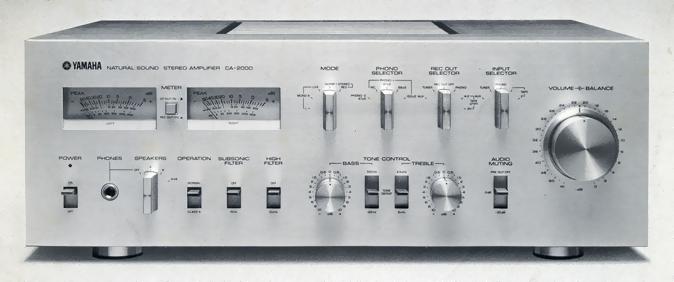
YAMAHA CA-2000
¥ 158,000 (around 1976)
Commentary
Aiming to be an artistic product of a pre-main amplifier, this pre-main amplifier has achieved a high level of perfection comparable to a separate amplifier by condensing Yamaha circuit technology.
The basic circuit configuration consists of an equalizer amplifier, a tone control amplifier, and a DC amplifier, a main amplifier capable of changing the volume between Class B and Class A, etc., and a head amplifier for MC cartridge.
The equalizer amplifier, tone control amplifier, and MC head amplifier have almost the same circuit configuration as C-2.
The circuit configuration of the main amplifier is as follows : FET differential amplifier with first stage current mirror cascode bootstrap → cascode connected constant-current load emitter-grounded amplifier → Darlington connected pure complimentary service Parapush OCL drive and output stage. The capacitor is removed from the signal path and NF loop.
The first stage consists of a differential amplifier using Yamaha's original super low-noise FET. The cascode bootstrap circuit eliminates signal degradation due to distortion factor even when the source impedance is high. The current mirror circuit is also assembled to ensure sufficient gain and low distortion factor.
In the second stage, the impedance of the current mirror output of the first stage is high, so the degradation of frequency characteristics due to the feedback capacitance of the transistor of the second stage is minimized, and it is cascode-connected constant-current load common-emitter amplification to obtain sufficient gain stably over a wide band.
The voltage of ± 70 v is supplied to the first and second voltage amplification stages from a constant-voltage power supply that is set separately from the drive and output stages.
The part following the voltage amplification stage is composed of a bias circuit unique to CA-2000. When the power supply voltage of the power amplification stage is switched by the switch, it is automatically classified as Class A (ID= 1.4A) ⇔ Class B (ID= 50 ma).
The power amplifier stage of the drive and output stage is a Darlington connection pure con parallel push-pull circuit in order to obtain a high output at a low distortion factor. By using the parallel push of transistors with good matching pair characteristics, the transistor can be used in a region with good linearity of hfe at the transistor operating point, and non-linear distortion can be reduced, making it possible to use the transistor with sufficient thermal margin.
In addition, the know-how obtained with the Yamaha FET preamplifier C-2 has been applied to the main amplifier section, and a high S / N ratio has been achieved by making the NFB circuit suitable for low noise and adopting a super low noise pair FET in the first stage.
When the operation of the output stage is switched to class A amplification, the collector loss becomes maximum when there is no signal and the heat generation of the transistor becomes large. However, the junction temperature of the transistor is reduced by adopting a heat sink with low thermal resistance and large heat radiation effect.
In addition, a PC limiter with two transistors is installed immediately before the drive and output stage. This limiter detects the voltage and current applied to the power transistor and protects the power transistor by controlling the input even when a load of 4 Ω or less is connected to the output terminal or when the output terminal is short-circuited.
The equalization circuit consists of a cascode bootstrap current mirror differential input using Yamaha original super low noise pair FET, a Darlington connection constant current load emitter-grounded, and a SEPP complimentary service stage with pure output.
The super low-noise pair FET (2SK-100) used in the first stage differential amplifier was developed by Yamaha for the equalizer of the CA 2000. Compared with the multi-use FET, it was specially designed for audio applications, especially for low-noise applications. Therefore, it has features such as large gm, good pair characteristics, and low noise (especially 1/f noise is suppressed).
The differential amplifier stage using super low noise Dual FET in the first stage assembles a current mirror cascode bootstrap circuit. The input is direct coupling without the input capacitor. This reduces the variation of phase characteristics in the low frequency range and enables low noise in the ultra low frequency range. The current mirror circuit obtains sufficient gain and works as a kind of push-pull circuit to cancel the even order harmonic distortion. In addition, by adopting the cascode bootstrap circuit, even if the signal source impedance changes greatly depending on the frequency such as when the MM type cartridge is connected, the distortion factor hardly deteriorates.
The second stage is a grounded emitter amplifier with a constant current load using a Darlington connection. This amplifier reduces the load on the first stage while maintaining sufficient gain.
The output stage is assumed to be approximately 15k Ω when the volume that can be considered as the load of the equalizer amplifier and the input impedance of the tape deck connected to the Rec out terminal are combined. The output stage is designed to have a low output impedance with a pure CON SEPP circuit using high ft transistors with well-matched pair characteristics, ensuring sufficient load stability. Also, the Rec out terminal uses a muting relay that prevents pop noise when the power is turned on or off.
The basic circuit configuration of the tone circuit is almost the same as that of the equalizer amplifier, and the second stage Darlington connection is omitted because it does not require as much gain as the equalizer amplifier.
A volume is inserted in the front stage of the tone amplifier. When the volume is reduced, the signal source impedance changes. However, since the cascode bootstrap circuit is adopted like the equalizer amplifier, the distortion factor does not deteriorate due to the change of the signal source impedance.
This tone amplifier has three functions : tone control, filter, and buffer amplifier. When these controls are not used, it operates as a buffer amplifier.
The tone control is a Yamaha NF type with low insertion loss and low noise design. The control volume uses a 20-step 21-position attenuator, and the turnover frequency can be switched between Bass and Treble.
Yamaha's original super-low-noise IC is used for the MC head amplifier to obtain a high SN ratio for the rated input.
This MC head amplifier is equipped with a low-level switch at 50 μ V on the input side. This was achieved by solving problems such as hum induction due to the leakage flux of the transformer, noise during switching, and the Seebeck effect of the switch contact. Even if an MC cartridge is attached to a player using an MM cartridge, there is no need to change the connection of the pin jack.
In order to improve the S / N ratio in actual use, two high-precision four volume loops per channel are placed on the input and output sides of the tone amplifier, and 0 to 6 dB, -24 to - infinity on the output side, and -6dB to -24dB on the input side are adjusted.
With this method, the residual noise when the volume is fully reduced is determined only by the main amplifier to minimize it. In addition, the high accuracy similar to that of the attenuator is achieved, and both the error from the displayed value and the gang error are small, making minute volume adjustment possible.
The peak meter uses a logarithmic compression circuit and a peak hold circuit to indicate the peak level of a signal in a wide range of -50dB to + 5 dB (0 dB = 100W/8 Ω) and 1 mW to 316W/8 Ω. The peak meter also has a fast rise time of 100 μ s and supports pulsed signals.
In addition, the meter is equipped with a switch to display the SP out output level and the Rec out output level.
Equipped with a Mode switch, you can choose Stereo Normal, Stereo Rev, L + R, L or R.
Equipped with a muting switch, -20dB muting is possible with just one switch.
Also, if this switch is set to the Pre out off position, the Pre out signal will not be output.
The preamp section and main amplifier section can be used separately.
In order to further improve low noise and low distortion rate, the equalizer sheet is directly connected to the rear panel, no shield wire is used, and the pattern of the printed circuit board is designed to minimize noise and distortion rate. The board through which low-level signals pass is strictly shielded.
In addition, operability is emphasized, and newly developed universal joints are used for the phono selector, rec out selector, and input selector to realize low noise, low distortion rate and improved operability.
.JPG)
.JPG)
.JPG)
.JPG)
Model Rating
| Type | Stereo pre-main amplifier |
| Effective output (0.03%, Aux) | 20 Hz to 20 kHz : 140W + 140W (4 Ω, Class B) 120W + 120W (8 Ω, Class B) 30W + 30W (8 Ω, Class A) 1 kHz : 180W + 180W (4 Ω, Class B) 130W + 130W (8 Ω, Class B) |
| Total harmonic distortion rate (20 Hz to 20 kHz) | Phono1, 2 → Rec out (5 V) : 0.003% or less Phono MC → Rec out (3 v) : 0.03% or less Tuner, Aux → Pre out (3 v) : 0.005% or less Main in → SP out (60W, Class B, 8 Ω) : 0.01% or less (15W, Class A, 8 Ω) : 0.005% or less Tuner → SP out (60W, Class B, 8 Ω) : 0.01% or less |
| Power bandwidth (0.03%, 8 Ω) | Class B : 10 Hz to 50 kHz Class A : 10 Hz to 70 kHz |
| Damping factor | 45 or More (8 Ω, 1 kHz) |
| Frequency characteristic | Phono 1, 2 mc (RIAA deviation) : 30 Hz to 15 kHz ± 0.2 dB Tuner-Pre out : 5 hz to 100 khz + 0 to 1 db Tuner-SP out (8 Ω load) : 5 Hz to 50 kHz + 0 -1dB |
| Input Sensitivity (Rated) / Impedance | Phono 1 : 2mV/47k Ω, 68k Ω, 100k Ω Phono 2 : 2mV/47k Ω Phono MC : 50 μ V/10 Ω Tuner, Aux : 120mV/50k Ω Main in : 1V/50k Ω |
| Maximum Allowable Input (1 kHz, 0.02% Distortion) | Phono1, 2 : 310 mVr. m. s Phono MC:7.5mVr.m.s Tuner, Aux : 20 vr. m. s |
| Output Level / Impedance | Rec out : 120mV/600 Ω Pre out : 1V/500 Ω |
| Tone control characteristics | Bass (125 Hz ⇔ 500 Hz) : ± 10 dB (20 Hz) Treble (8 kHz ⇔ 2.5 kHz) : ± 10 dB (20 kHz) |
| Subsonic Filter | 15 Hz, 12dB/oct. |
| High filter | 10 Hz, 12dB/oct. |
| Noise Level / SN Ratio (IHF-A Network) | Phono1, 2 : 82 dB Phono MC : 71 dB (input 50 Ω short) 68 dB (input 0 Ω short) Tuner, Aux, Tape : 100 dB Main:118dB |
| Residual noise | 0.07 mV or less |
| Meter Section | |
| Indication range | -50dB to + 5 dB |
| Response speed | 100 μ s |
| Return speed | 0.95sec |
| <Others> | |
| Pwer | 100 VAC, 50Hz/60Hz |
| Rated power consumption | 300W |
| External dimensions | Width 461x Height 170x Depth 360 mm |
| Weight | 20kg |