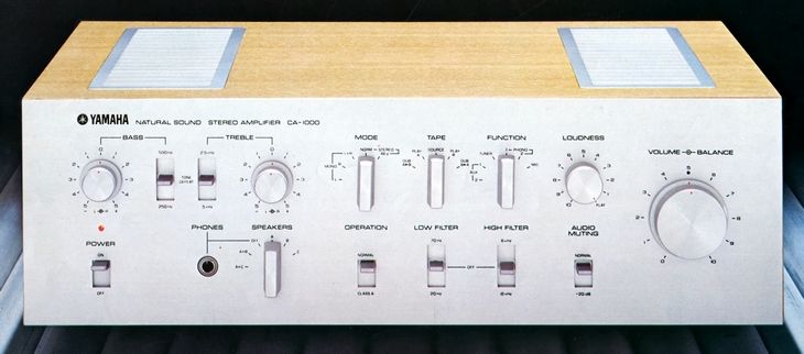
YAMAHA CA-1000
¥ 98,000 (released in 1973)
Commentary
This is a stereo pre-main amplifier that uses a main amplifier with class-B to class-A operation switching.
The main amplifier section uses a pure complimentary service OCL circuit directly connected to all stages without interstage condenser.
Furthermore, high stability is obtained by a bias stabilization circuit using two differential amplifiers and transistors, and an FET is used for the bias circuit of the first differential amplifier, and ideal bias characteristics are obtained by its constant current characteristics.
The operation mode of the power stage is switched between class B and class A. Stable power of class B and low distortion of class A can be freely selected.
The power supply section is equipped with a large-core power transformer with excellent regulation, a 18000 μ Fx2 capacitor, and a high-capacity rectifying diode with a surge current of 250A.
In addition, a separately set constant voltage power supply that drives all stages except the power stage has been adopted to improve the stability of the whole amplifier.
The protection circuit contains two stages, one for the power transistor and the other for the speaker.
The power transistor protection circuit operates quickly in the order of μ S against overload. Even if the load drops below 2 Ω or the output terminal is short-circuited, the protection circuit instantaneously differentiates to prevent troubles. Since this circuit is an input limiter type, the output only decreases while the protection circuit is operating, and playback is not interrupted.
The speaker protection circuit uses Yamaha's original circuit method. When the DC voltage at the output terminal exceeds ± 2 V, the relay immediately differentiates and cuts off the signal path to the speakers. When the voltage falls within ± 2 V, it automatically returns. It also functions as a power muting, so there is no shock noise caused by rush current when the power switch is turned on.
The SRPP type FET is used in the first stage of the equalizer amplifier, and the secondary distortion is greatly improved compared with the single type FET. The FET has advantages such as very little pulse noise compared with the transistor, and the noise figure decreases as the source impedance becomes higher.
In addition, a high supply voltage of + 50 v and a SEPP output stage with low output impedance provide high output at a low distortion rate and a sufficient dynamic margin.
The equalizer consists of a combination of a metal-coated resistor (± 1% error) and a styrene capacitor (± 1% error, ± 2% error), and a tantalum capacitor with less leakage current and aging.
The Phono1 circuit is equipped with an input impedance selection switch to adjust the load impedance of the cartridge to the optimum value. It also has a built-in head amplifier for the MC cartridge so that the MC cartridge can be directly connected without a step-up transformer.
In addition, the Function switch is mounted on the equalizer board, and measures against external noise such as wiring and shielding case are taken to improve sound quality.
The tone control circuit uses a 3-stage direct-coupled amplifier and Yamaha mixing NF and CR types. By carefully selecting low-noise transistors, residual noise is reduced and high SN and low distortion factor are realized.
In the Tone Defeat position, the circuit operates as a flat amplifier.
The filter circuit consists of a 3-stage direct-coupled amplifier with an emphasis on phase characteristics and distortion factor.
The cut-off frequency of both low filter and high filter can be switched by 2 stages.
The loudness circuit employs a continuously variable type of continuous loudness control that provides a volume dedicated to the loudness and enables adjustment based on the actual listener's ear.
Equipped with a pre-main coupler that can be used separately for the pre-amplifier and main amplifier.
Equipped with audio muting.
It is equipped with a special amplifier for the microphone to prevent sound quality degradation due to time constant switching of the equalizer.
.JPG)
.JPG)
Model Rating
| Type | Pre-main amplifier | ||||||||
| Main Amplifier Section | |||||||||
| Circuit system | Class B and Class A operation switching type all stages directly connected pure complimentary service SEPPOCL circuit | ||||||||
| Dynamic Power (IHF) | Class B operation : 200W (8 Ω) | ||||||||
| Effective power |
|
||||||||
| Total harmonic distortion factor |
|
||||||||
| Cross modulation distortion factor (70Hz:7kHz=4:1) |
|
||||||||
| Power bandwidth (IHF, both channel drive) |
Class A operation : 5 Hz to 100 kHz Class B operation : 5 Hz to 50 kHz |
||||||||
| Frequency characteristic | 10 Hz to 100 kHz + 0 -1dB | ||||||||
| Input Sensitivity / Impedance | Class A operation : 330mV/40k Ω Class B operation : 775mV/40k Ω |
||||||||
| Output terminal | Speaker jacks : Route 3 Headphone terminal : 4 Ω ~ 16 Ω |
||||||||
| Damping factor | 70 (1 kHz, 8 Ω) | ||||||||
| Signal-to-noise ratio (IHF, A-network) | 100dB | ||||||||
| Residual noise | 0.8 mv (Pre + main amplifier, 8 Ω) | ||||||||
| Preamplifier Section | |||||||||
| Circuit system | Equalizer amplifier : FETSRPP Input, TrSEPP Output 6-Stone Amplifier Microphone Amplifier : 2-Chip Direct Connection Amplifier Control Amplifier : Intermediate Emitter-Follower 3-Chip Connected Amplifier |
||||||||
| Input Sensitivity / Impedance | Phono1 MC : 200 μ V/100 Ω Phono1 : 3mV/50k Ω, 100k Ω Phono2 : 3mV/50k Ω MIC : 2.5mV/50k Ω Tuner, AUX1, 2, Tape PB A, B : 120mV/40k Ω |
||||||||
| Output Level / Impedance | Rec outA, B : 120mV/2k Ω Pre out : 775mV/2k Ω |
||||||||
| Phono maximum allowable input (1 kHz) | 310mVrms(870mVp-p) | ||||||||
| Frequency characteristic | Phono (RIAA deviation) : 30 Hz to 15 kHz ± 0.2 dB MIC : 20 Hz to 20 kHz + 0. 5-2 dB Tuner, AUX, Tape PB : 10 Hz to 50 kHz + 0.5 -1dB |
||||||||
| Signal-to-noise ratio | Phono1 MC:70dB Phono1, 2 MM : 80 dB MIC:70dB Tuner, AUX, Tape : 90 dB |
||||||||
| Tone control | Bass : ± 15 dB (50 Hz), Turnover Frequency : 250 Hz, 500 Hz Treble : ± 10 dB (10 kHz), Turnover Frequency : 2.5 kHz, 5 kHz |
||||||||
| Filter | Low : 20Hz/70Hz, 12dB/oct. High : 6kHz/12kHz, 6dB/oct. |
||||||||
| Loudness control | Continuous loudness corresponding to an equal loudness curve | ||||||||
| Audio Muting | -20dB | ||||||||
| <General> | |||||||||
| Power supply voltage | 100 VAC, 50Hz/60Hz | ||||||||
| Power consumption | Rating : 250W Maximum : 420W |
||||||||
| AC outlet | Power switch interlock : 2 systems, max200W Power switch not interlocked : 2 systems, max200W |
||||||||
| External dimensions | Width 436x Height 144x Depth 323 mm | ||||||||
| Weight | 15.5kg | ||||||||
.jpg)