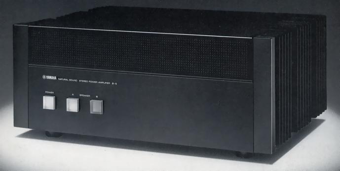
YAMAHA B-5
¥ 250,000 (around 1979)
Commentary
Stereo power amplifier with linear transfer circuit and all-FET circuit configuration.
The basic circuit configuration of B-5 is as follows : the first stage is a cascode bootstrap differential-amplifier circuit using low-noise High-gm Dual FET, the pre-drive stage is a cascode connected current-mirror push-pull differential-amplifier circuit, and the drive stage is a pure complimentary service triple-push-pull OCL using a 3-stage emitter-follower with a linear-transfer circuit.
In the development of the B-5, an HP-IB audio analyzing system, which combines a computer and a spectrum analyzer, was introduced and designed after measuring all the data. This HP-IB system can analyze harmonic distortion components over 2nd to 10th order in terms of distortion in the order of 0.00005%, and can examine frequency characteristics in the order of 0.01 dB over 10 MHz.
The first stage consists of a low-noise, high-gm Dual FET with a balanced feed differential amplifier circuit and a cascode bootstrap circuit. This Dual FET combines the electrical and thermal characteristics of the two low-noise, high-gm FETs in the same package. This FET has sufficient characteristics as the first stage element of a DC amplifier. The assembled cascode bootstrap circuit consists of the V of the Dual FET.DSCan be operated at the lowest value in the active region of the FET, preventing distortion degradation at the input terminal due to changes in drain / gate leakage current.
The pre-drive stage is a push-pull differential amplifier circuit using a cascode-connected current mirror circuit. Since this current mirror circuit performs class A push-pull operation, even order harmonic distortion is suppressed very little, and sufficient amplification degree is obtained as a voltage amplifier stage.
The FET of the first stage and pre-drive stage can be charged with a large capacity by passing a current of 5 mA or more. The response characteristic to the transient signal is also good, and there is no internal clip in the transient.
The output stage uses a newly developed copper stem high-fT transistor with a maximum collector loss (Pc) of 150W, a maximum collector current (Ic) of 15A, and a breakdown voltage (V).CBOAlthough it is a high power type of 180 v, the upper limit frequency is as high as 90 mhz (typ) for NPN type 2SC2707 and 70 mhz (typ) for PNP type 2SA1147. Switching distortion, which is a defect when conventional bipolar transistors are operated in class B operation, is greatly reduced. The linearity of hfe, which is related to the distortion factor of the amplifier, is also excellent over a wide current range for both NPN and PNP types.
In addition, copper stem is used for the case of the power transistor instead of conventional iron, socket and mounting screw are also made of copper, and non-inductive copper terminal resistor is used for the emitter resistor of the power stage in which a large current flows. In addition, copper, which causes little degradation of sound quality, is used for all parts in which a large current flows.
A 3-stage emitter-follower pure complimentary service triple push-pull DC-amplifier with a linear transfer circuit is used for the power amplifier stage. With a 3-stage configuration of high-fT transistors with well-matched pair characteristics, sufficient power gain can be obtained over a wide band. At the same time, the carrier discharge speed in the class B operation region is increased at each stage, preventing degradation of frequency characteristics and distortion factor in the high-frequency range, and ensuring high stability in no-load conditions.
The B-5 uses a linear transfer circuit to greatly reduce crossover distortion.
In the linear transfer circuit, three power transistors used in triple push-pull are biased by a unique circuit configuration to shift the operating point of each transistor, and the composite transfer characteristic for small signals is close to the square characteristic to obtain linear characteristics and suppress crossover distortion.
We are the first in the world to use an aluminum electrolytic capacitor exclusively for audio that uses a polypropylene case for the power circuit.
In the case of the conventional aluminum case, the electromagnetic field radiated by the electric current flowing through the aluminum foil is distorted by the aluminum case, resulting in an adverse effect on the audio signal. However, the adoption of the polypropylene case solves this problem.
In the internal structure, the power factor of the electrode foil is reduced to about half of that of the conventional one. Moreover, the high-speed electrolytic solution is adopted, the number of lead leads is increased by 50%, the terminals are brought as close as possible to reduce the loop between the electrodes, and the impedance is reduced. In addition, vibration is suppressed by tightening the winding of the aluminum foil, and there are no dissimilar metal joints in the terminal structure. This is one of the other features that have been examined in detail even though it does not appear in the characteristics.
The power supply circuit uses an audio electrolytic capacitor that uses a highly regulated large-capacity toroidal transformer and a polypropylene case. In addition, to compensate for the high-frequency limit of the capacitor, a Yamaha custom audio Meiler film capacitor is connected in parallel to suppress the rise of the power supply impedance in the high-frequency range.
In B-5, the power amplifier stage is a three stage Darlington connection. The power supply for the emitter follower of the first stage is supplied from the ± 80 v constant voltage power supply of the pre-drive stage, and the power supply for the drive transistor of the second stage is supplied from the ± 10 v stacked power supply from the ± B power supply. This ensures stable amplification from very small signals to large amplitude signals.
In addition, independent local constant-voltage power supplies are provided for the first stage and predrive stage, which are voltage amplification stages, to improve isolation between the power supply side and the signal side, and to improve crosstalk between L/R due to IM distortion and common impedance caused by the influence of the power supply.
In order to protect the power transistor from overload conditions such as short-circuited speakers and low impedance loads of 4 Ω or less, a Pc limiter circuit is mounted to detect power transistor loss (Pc) and limit driving.
When DC is input to the input terminal or when DC voltage leaks to the output terminal due to an error in the amplifier, a speaker protection circuit is used to detect the DC voltage and disconnect the speaker circuit by relay.
This relay uses a high-power shut-off type equipped with an arc blow-out device using a magnet and a parent / child contact with staggered timing, ensuring long-term stable operation.
In order to protect the speakers from shock noise generated when the power switch is turned on, a muting circuit is installed to disconnect the speakers for approximately 5 seconds until the amplifier becomes normal operation.
The main circuit uses quality parts such as tantalum nitride resistance, polypropylene film capacitor, mica capacitor, printed circuit board using 70 μ pressure copper foil, 2 mm thick bus earth, and input / output terminal with gold plating.
In addition to the pin jack dedicated to DC input, the amplifier is equipped with an AC input terminal with a DC component cut off by inserting a high-quality Mylar film capacitor. This prevents the deterioration of sound quality due to the contact of the AC-DC changeover switch and protects the amplifier from harmful DC leakage with a cutoff frequency of 6.4 Hz.
Equipped with two speaker output jacks.
The two connected speakers can be switched in four ways, A/B/A + B/OFF, by means of the illuminated changeover switch on the front panel.
Equipped with left and right independent input level control.
.JPG)
.JPG)
.JPG)
.JPG)
.JPG)
Model Rating
| Type | Stereo power amplifier | ||||
| Rated output |
|
||||
| Power Bandwidth (8 ω, 120W) | 10 Hz ~ 100 kHz (Distortion 0.01%) | ||||
| Damping factor | 200 (8 Ω, 20 kHz) | ||||
| Input Sensitivity / Impedance | 1V/25k Ω (470 pF, 8 Ω, 100W) | ||||
| Frequency Response (8 Ω, 120W) |
|
||||
| Total Harmonic Distortion Factor (120W, 8 Ω) | 0.003% or Less (10 Hz to 20 kHz) 0.007% or Less (10 Hz to 50 kHz) 0.01% or Less (100 kHz) |
||||
| Intermodulation distortion rate (60 Hz : 7 kHz = 4 : 1, 8 Ω, 120W) | Not more than 0.002% | ||||
| Signal-to-noise ratio (IHF-A network, Vol. max, RL = 8 Ω) | 123 dB or more | ||||
| Filter | -6dB/oct, fc = 6.4 Hz | ||||
| Channel Separation (8 Ω) | 1kHz:100dB 20kHz:95dB 100kHz:70dB |
||||
| Pwer | 100 VAC, 50Hz/60Hz | ||||
| Rated power consumption | 560W | ||||
| External dimensions | Width 435x Height 182.7x Depth 361.5 mm | ||||
| Weight | 20.9kg |