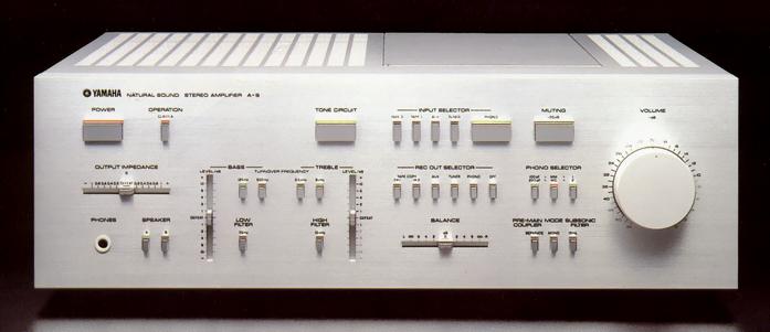
YAMAHA A-9
¥ 245,000 (around 1979)
Commentary
This pre-main amplifier was announced as Yamaha's new top-of-the-line amplifier following the CA 2000 series.
The basic circuit configuration of A-9 is a class A / B switching type DC main amplifier equipped with a pure current servo amplifier type DC equalizer, a pure current servo amplifier type flat amplifier, and a new linear transfer circuit.
If necessary, a low-noise MC head amplifier and a pure current servo amplifier tone control amplifier can be inserted.
The A-9 uses a pure current servo amplifier preamplifier circuit.
This pure current servo amplifier uses a system in which no signal current flows through the power supply or ground line, and a constant current is always supplied through the power line. This realizes 0 element sensitivity, which is not affected by not only the L/C/R components of the power supply and wiring, but also the non-linear power supply system due to current changes.
In addition, the pure current servo amplifier is less affected by ground impedance because no signal current flows to the ground, and low-frequency crosstalk is improved. In addition, the loop of output current is small because current is taken in and out of the load inside the amplifier, and the effect of flux generated from the loop is minimized.
The DC equalizer circuit of the pure current servo amplifier system is used for the equalizer amplifier section. By adopting the pure current servo amplifier system, the change in the current supplied to the amplifier is reduced to less than 1 / 100 compared with the case of only the class A amplifier section, and the element sensitivity of the power supply section is reduced to almost 0 by that amount.
The basic circuit configuration of the equalizer amplifier section is a DC amplifier configuration of the first stage of low-noise dual FET differential and the SEPPUCCI output stage.
The flat amplifier section also uses a DC amplifier that uses the pure current servo amplifier method similar to the equalizer amplifier section.
One chip dual FET and one chip dual transistor are used for the first stage to suppress DC drift. A three legged metal-coated dual resistor is also used for the two resistors for differential current balance. By using these one chip dual FET/TR / resistors, the time drift from the time when the power switch is turned on to the steady state and the transient and steady change of the ambient temperature are greatly improved. In addition, two metal-glazed volume, coarse adjustment and fine adjustment, are used to increase the offset adjustment accuracy of DC.
The tone control amplifier circuit consists of a differential-input current mirror cascode bootstrap circuit using a low-noise FET, a pure complimentary service SEPP-OCL circuit, and a pure current servo amplifier system.
The cascode bootstrap circuit assembled in the first stage prevents the distortion factor from increasing due to the signal source impedance fluctuation when the filters inserted in the previous stage are operated. The tone control circuit is set to 0 dB gain so that the gain of the whole amplifier does not decrease even when disconnected from the signal path by the Tone Circuit switch.
The Yamaha NF-type tone control system is used for this product. In addition to providing excellent control characteristics, the characteristics become flat at the time of defeat, and the turnover frequency can be switched between two levels for both Bass and Treble.
A 12dB/oct active filter is used for the low filter and high filter, and a buffer amplifier is used to obtain more accurate attenuation characteristics.
The MC head amplifier uses six low-noise transistors with low rbb' (base resistance) and large hfe to reduce voltage noise. The basic configuration is 2-stage differential amplification -SEPP output. The time constant in the low-frequency range is small, SVRR is greatly improved, and it is less affected by the power supply.
In addition, the coupling capacitor, which especially affects sound quality, uses a capacitor in a plastic case for audio only.
The main amplifier circuit consists of the first stage with dual FET source follower circuit and cascode complimentary service differential circuit, pre-drive stage with cascode complimentary service circuit, and drive / complimentary service stage with 3-stage Darlington pure output parallel push-pull OCL.
The switching distortion characteristic of Class B amplifiers is suppressed to a level that cannot be observed even at a high frequency of 100 kHz by using a High-fT transistor, and the crossover distortion characteristic of Class B amplifiers is greatly reduced by installing a newly developed new linear transfer circuit.
This new linear transfer circuit detects and feeds back the bias change of the final stage of the power amplifier to the bias circuit, and is equivalent to V.BELinearity has been improved and crossover distortion has been greatly reduced.
With A-9, operation of class B power amplifier with new linear transfer circuit can be switched to pure class A operation by switching operation switch.
In terms of circuitry, when the operation switch is switched to classA, the power supply voltage at the final stage of the power amplifier is switched from ± 65 v to ± 30 v, and the idling current is switched from 80 ma to 1.4A upon detection of the voltage.
The A-9 is equipped with an Ro (output impedance) control that can continuously vary the output impedance of the main amplifier from + 1 Ω to 0 Ω to -1 Ω. The Ro control allows you to change the Q, which is related to the damping characteristics of the speaker, in the amplifier without operating the speaker system. You can obtain the desired sound by controlling the Q characteristics of the speaker system and the DC resistance of the speaker cable from the amplifier side.
For example, if the Q is relatively high and the frequency response near fo has a few peaks, you can obtain a flat response by setting Ro to the - side, and if the Q is relatively low and the frequency response is slightly overdamped, you can obtain a flat response by setting Ro to the + side.
The power supply section is equipped with a high-capacity toroidal transformer and an electrolytic capacitor (15,000 μ Fx4) in a plastic case for audio equipment. The transformer has separate windings for the left and right channels and is rectified separately for the left and right using a high-speed diode. Therefore, adverse effects such as crosstalk between both channels are minimized.
The front part is located on the front side and the power amplifier and power supply part are located on the rear side. This construction smooths the signal flow and reduces interference between the left and right channels and between each circuit.
In addition, the pin jack of the preamplifier section is located on the sub-panel just behind the front panel to eliminate shield wires that degrade sound quality. In addition, plastic and aluminum are used on the top panel and side panel to reduce adverse effects caused by metal and magnetic materials.
Yamaha's original audio coupling capacitors, high-speed diodes, gold-plated -speed diodes, gold-plated phono terminals, high-precision four volume units, and push switches with indicators are used.
In order to improve the S / N ratio in actual use, a high-precision 4-series volume is adopted, and 2 series volumes per one channel are inserted into the input side and output side of the flat amplifier. This greatly improves the characteristics of reducing the volume in actual use.
The muting relay used for the pre-out and headphone output does not enter the series of signal paths as in the past, and is designed so that the signal does not pass through the relay when it is in use, thus suppressing sound quality degradation due to contact points.
Equipped with -20dB audio muting.
Equipped with a Rec out selector.
Equipped with a subsonic filter.
.JPG)
.JPG)
.JPG)
.JPG)
.JPG)
.JPG)
.JPG)
.JPG)
.JPG)
Model Rating
| Type | Pre-main amplifier | ||||
| Rated output (both channel drive 20 Hz to 20 kHz, Main in-SP out) |
|
||||
| Power bandwidth (Main in-SP out, 8 Ω) |
Class A : 10 Hz to 100 kHz (0.007%, 15W) Class B : 10 Hz to 100 kHz (0.01%, 60W) |
||||
| Damping factor | Variable in the range of -8 ~ 200 ~ + 8 (8 Ω, 1 kHz) | ||||
| Input Sensitivity / Impedance (resistance + capacitance) |
Phono1, 2 mc : 100 μ V/100 Ω Phono1, 2 mm : 2.5mV/47k Ω (100pF/220pF) Tuner, Aux, Tape1, 2 : 150mV/47k Ω Main in : 1V/10k Ω |
||||
| Maximum Allowable Input (1 kHz, 0.005%) | Phono1, 2 : MC : 11 mV Phono1, 2 mm : 280 mV Tuner, Aux, Tape1, 2 : 17 v |
||||
| Output Voltage / Impedance / Maximum Output (1 kHz, 0.005%) |
Rec out1, 2 : 150mV/220 Ω / 17 v Pre-out : 1V/600 Ω or less / 3 V |
||||
| Frequency characteristic | Phono-Rec out (RIAA deviation) : 20 Hz to 20 kHz ± 0.2 dB Tuner-SP out : 4 Hz to 100 kHz + 0 to 0.5 dB |
||||
| Total harmonic distortion factor | Phono1, 2 MC-Rec out (5 v) : 0.005% Phono1, 2 MM-Rec out (5 v) : 0.002% Tuner, Aux, Tape-Pre out (2 v) : 0.001% Tuner, Aux, Tape-SP out (60W, 8 ω, Class B) : 0.0025% Tuner, Aux, Tape-SP out (15W, 8 ω, classA) : 0.002% |
||||
| Signal-to-noise ratio (IHF-A network) | Phono1, 2 mc : 74 dB Phono1, 2 mm : 88 dB Tuner, Aux, Tape1, 2 (Tone off) : 110 dB Tuner, Aux, Tape1, 2 (Tone on) : 102 dB Main:120dB |
||||
| Tone Control Variable Width | Bass : ± 10 dB (20 Hz, turnover 500 Hz) Treble : ± 10 dB (20 kHz, turnover 2.5 kHz) |
||||
| Turnover frequency | Bass : 125 Hz, 500 Hz Treble : 2.5 kHz, 8 kHz |
||||
| Filter characteristic | 15 Hz, 12dB/oct. 70 Hz, 12dB/oct. 10 kHz, 12dB/oct. |
||||
| Channel separation (Volume -30dB, 1 kHz) |
MC-SP out (input short circuit) : 75 dB or more MM-SP out (input 5.1k Ω) : 70 dB or more Tuner-SP out (input 5.1k Ω) : 70 dB or more |
||||
| Audio Muting | -20dB | ||||
| Headphone out | 100 mW (8 Ω, at rated output) | ||||
| Headphone output impedance | 270 Ω | ||||
| Rise time | 1 μ sec (8 Ω Load, Tuner in) | ||||
| AC outlet | switched:total 100W max unswitched:total 200W max |
||||
| Power consumption | 375W | ||||
| External dimensions | Width 460x Height 155x Depth 426 mm | ||||
| Weight | 21kg |