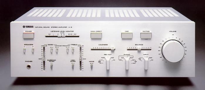
YAMAHA A-8
¥ 169,000 (around 1981)
Commentary
A pre-main amplifier with Yamaha amplifier technology and a main amplifier equipped with a linear transfer circuit supported by X power supply and a preamplifier section using a pure current servo amplifier.
The basic circuit configuration is simple : DC equalizer amplifier with new pure current servo amplifier system → high-gain DC main amplifier with linear transfer circuit.
If necessary, an MC head amplifier with a complimentary service push-pull FET differential input and an NF-CR tone control circuit can be inserted.
The MC head amplifier uses a pure current servo amplifier with a circuit configuration applicable to the power supply : complimentary service push-pull FET input → complimentary service push-pull output.
Since the first stage complimentary service push-pull operates the FET with the same characteristics at the source ground, the second order characteristics of the FET cancel each other and the generation of distortion is suppressed to a low level. The non-linearity of the input capacitance is also expected to be cancelled because the P-P operation is performed for the input signal. The internal resistance of each FET, which is a noise source, is doubled as the noise source impedance in the case of general complimentary service amplification. However, in the case of differential push-pull, the internal resistance of each FET, which is a noise source, is reduced to 1/2 because of AC-parallel operation, and a high SN ratio can be secured.
In addition, in order to handle especially weak signals, a constant current circuit and pure current servo amplifier system are adopted to eliminate noise generated by various non-linear components and noise from the power supply side.
The MC head amp has a 10k Ω position in addition to the orthodox 100 Ω position.
This input is designed in consideration of the fact that the larger the input impedance of the amplifier, the smaller the nonlinear effect such as poor contact in the middle becomes. The structure of this input is such that 0.01 μ F is put in parallel with the load resistance to the MC input, which used to have low load characteristics because it is easy to oscillate when it is received at high impedance, so the resonance frequency is lowered and stability is ensured by damping to Q = 2 or less. At the same time, unnecessary band components of several hundred kHz or more are attenuated at 12dB/oct.
In the equalizer amplifier section, the first stage is a differential input by High-gm Nch FET and the second stage is also a differential amplification by High-gm Pch FET. The final stage emitter follower is equipped with a pure current servo II. The current of the amplifier as a whole is supplied by a pure current servo I. This thoroughly suppresses the power supply current variation and minimizes adverse effects from the power supply.
In terms of the circuit, the output impedance of the first stage is high because the load for the first stage differential is a constant current load and the first stage High-gm FET is used in the cascode bootstrap. Furthermore, since the second stage is received by the P-type High-gm FET, the gain of the first stage is high without using a circuit with unstable elements such as PFB (positive feedback). In this configuration, the FET is operated with a constant voltage load by the cascode circuit as a voltage amplification element, and the differential push-pull is used. Therefore, as a result of the ideal square characteristic push-pull, the generation of distortion in the open loop is minimized. In addition, by dividing the middle and low frequencies into the NFB type and the higher frequencies into the CR type, accurate RIAA characteristics over a wide band and excellent characteristics are achieved.
In addition, two types of pure current servo are used in the equalizer stage. Pure Current Servo I was developed with the head amplifier HA-2. It consists of a constant current source in series and a parallel constant voltage circuit in the amplifier section. It stabilizes the power supply current and insulates noise from the power supply side.
The Pure Current Servo II detects changes in the power supply current and applies a servo to the parallel current absorption circuit so that the detected changes converge to 0. Thus, the Pure Current Servo II effectively keeps the power supply current constant and makes the power supply impedance seen from the amplifier side 0.
The main amplifier circuit is a two stage differential amplifier with a dual FET differential input as the first stage. All the circuits are cascode connected, so that low distortion rate characteristics are obtained up to large amplitude and high frequency.
In the power stage, the linear transfer circuit developed in the separate power amplifier B-5 is adopted. The bias voltage is fixed, and each operating point of the power transistors connected in parallel is shifted so that the composite characteristic approaches the square characteristic and the linear total transfer characteristic is achieved. Smooth current waveform and low distortion factor characteristics with little crossover distortion are obtained from minute output to large output.
The power transistor used is a Pc100W, Icmax10A high-speed power transistor with a single-channel total collector loss of 1200 total collector loss of w and a total fine collector current of 30A. As a result, a large speaker the X power supply, large speaker drive capability is obtained, power stage gm is increased, distortion under constant impedance load is reduced, and thermal operation stability against music signals, etc. is improved.
An X power supply is used for the power supply section, which uses an AC control element, TRIAC, and a reference voltage comparator. It controls the conduction phase angle of the voltage waveform applied to the primary side of the power transformer, and supplies power at high speed with the precision required according to the dynamic range of music.
As a result, the output stage of the main amplifier section can be set to a constant voltage, which was impossible with conventional power supplies. At the same time, the low temperature of the amplifier with good regulation can be obtained.
For the frame structure of the amplifier, an assembly method similar to the power transistor mounting structure is adopted, and insulation points and conduction points are clarified to realize a loop-less structure.
The chassis surface is plated with copper plated with copper and the surface layer is a conductive layer that does not show magnetic properties, thereby reducing the sound quality degradation caused by iron. In addition, high-purity copper foil with a thickness of 35 μ m is used for the electric shield material that does not require strength, and the bottom cover is made of plastic to prevent eddy current loss.
The Chemi-Con in the power supply section, which has a significant effect on sound quality, uses a capacitor in a plastic case, an improved version of the one used in the A-9. The Chemi-Con in other signal paths also uses a plastic case.
In addition, tantalum nitride resistors are used for NFB circuits and other circuits with high element sensitivity. These resistors have excellent voltage distortion factor, resistance value stability, and low power supply noise.
We also use quality parts that we have developed and carefully selected, such as polypropylene capacitors, Mylar capacitors, and mica capacitors.
The main direct switch is mounted. By turning it ON, various controls can be jumped and a signal can be directly input to the main amplifier.
.JPG)
.JPG)
.JPG)
.JPG)
.JPG)
Model Rating
| Type | Stereo pre-main amplifier |
| Effective output (20 Hz to 20 kHz, 0.003%) | 150W + 150W (8 Ω) |
| Power Bandwidth (75W, 0.002%) | 10 Hz ~ 100 kHz (8 Ω) |
| Damping factor | 200 (8 Ω, 1 kHz) |
| Input Sensitivity / Impedance | Phono MM : 2.5mV/100k Ω, 47k Ω, 33k Ω, 100 Ω Phono MC : 100 μ V/100 Ω, 10k Ω Tuner, Aux, Tape : 150mV/47k Ω |
| Maximum Allowable Input (1 kHz, 0.01%) | MM:280mV MC:11mV |
| Output Level / Impedance | Rec out : 150mV/560 Ω |
| Headphone Output / Impedance | 84mW/8 Ω (0.01%) |
| Frequency Response (Main Direct on) | Tuner, Aux, Tape : 20 Hz to 100 kHz + 0 to 1.0 dB |
| RIAA deviation (20 Hz to 20 kHz) | MM : + / - 0.2 dB MC : + / - 0.2 dB |
| Total harmonic distortion rate (20 Hz to 20 kHz) | Phono MM → Rec out (10 V) : 0.003% Phono MC → Rec out (10 v) : 0.003% Tuner, Aux, Tape → SP out (Main Direct on, 150W) : 0.003% |
| Intermodulation distortion factor (Tuner, Aux, Tape, 8 Ω) | 0.002% (at rated output) 0.01%(1W) |
| Signal-to-noise ratio (IHF-A network Input short) |
Phono MM:88dB Phono MC:70dB Tuner, Aux, Tape : 110 dB (Main Direct on), 96 dB (Main Direct off) |
| Input Reduced Noise (IHF-A Network) | Phono MM : 0.1 μ V Phono MC : 0.03 μ V |
| Residual Noise (IHF-A Network) | Main Direct on : 80 μ V Off : 500 μ V |
| Channel separation | Phono MC : 70 dB (0 Ω, Vol -30dB) |
| Tone control characteristics | Turnover frequency Bass : 125 Hz, 500 Hz Treble : 2.5 kHz, 8 kHz Maximum variable width Bass : + / - 10 dB Treble : + / - 10 dB |
| Filter characteristics | Subsonic Filter : 15 Hz, 12dB/oct. High Filter : 10 kHz, 12dB/oct. |
| Continuous loudness control | -20dB (based on 1 kHz, maximum correction amount, sound correction curve) |
| Audio Muting | -20dB |
| Tracking error | -20dB |
| Slew rate | 200 V / μ sec |
| Semiconductor used | Transistor : 111 units FET : 10 IC : 4 Diode : 63 units LED : 10 pcs |
| AC outlet | Interlocking : 2 systems (100W) Non-linked : 1 system (200W) |
| Pwer | 100 VAC, 50Hz/60Hz |
| Rated power consumption | 240W |
| External dimensions | Width 435x Height 144x Depth 422 mm |
| Weight | 12.5kg |