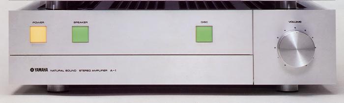
YAMAHA A-1
¥ 115,000 (around 1977)
Commentary
A pre-main amplifier with simple design and straight DC & DC configuration.
The circuit configuration of A-1 is as simple as a low-noise MC head amplifier, DC equalizer amplifier and DC high gain main amplifier when the DISC switch is ON. When the DISC switch is OFF, all functions contained in the sealing panel can be selected, and a 0 dB gain tone control circuit can be used as needed.
This circuit configuration is achieved by allowing the high gain main amplifier to receive the gain of around 20 dB, which is normally received by the tone amplifier. In the straight DC configuration, there is only one film capacitor between the DC equalizer amplifier and the DC main amplifier.
The equalizer circuit consists of a DC amplifier without the capacitor of the input circuit and the electrolytic capacitor of the NFB circuit. The first stage is equipped with a current mirror cascode bootstrap circuit using Yamaha's original super low-noise Dual FET. The output stage is a SEPP circuit using transistors. The output impedance is designed to be as low as 600 Ω, ensuring sufficient load stability.
The Rec out uses a muting relay to prevent pop noise when the power is turned ON / OFF.
The frequency characteristics of the MM type cartridge differ depending on the input impedance of the amplifier, and the optimum load resistance also differs depending on the cartridge. Therefore, in A-1, the specified load resistance value is obtained by inserting the attached Cartridge Load plug (47k Ω, 68k Ω) into the Cartridge Load terminal on the rear panel, or 100k Ω when the Cartridge Load plug is not inserted.
The main amplifier is designed to have an input sensitivity of 200 mV, so the gain is approximately 20 dB higher than that of a normal main amplifier.
The first stage consists of Yamaha's original low-noise Dual FET differential amplifier, the pre-driver stage consists of a current mirror load differential amplifier circuit, the buffer amplifier consists of an emitter follower, and a Darlington SEPPPOCL DC amplifier.
As a countermeasure against the drift of center voltage, which is a problem in DC amplifier, we have adopted Yamaha original Dual FET which contains FET with good electrical and thermal characteristics in one package. We have also taken sufficient consideration of circuit structure and component arrangement to minimize temperature drift and time drift of center voltage.
F is the transistor used for each stage.TIn particular, the output-stage transistors have good complimentary service characteristics, are mounted on a large heat sink, and have a sufficiently low distortion factor beyond the audible band.
A low-noise element is used in the MC head amplifier section to achieve a high SN ratio.
The tone control circuit uses Yamaha's original NF-CR type, which has excellent control characteristics.
This tone circuit also functions as a 10 Hz, 12dB/oct subsonic filter. If the control knob is set to the flat position, only the subsonic filter can be operated.
The power supply circuit employs two high-capacitance transformers arranged to cancel the leakage flux of each transformer and connected to the para. The capacitor employs a high-capacitance capacitor of 18,000 μ Fx2 that has been carefully examined for sound quality. In addition, the power supply impedance is reduced by connecting a metallized ドマイラ capacitor of 2.3 μ F to the para.
The protection circuit is equipped with a transistor protection circuit using a PC limiter and a speaker protection circuit which also functions as muting by detecting the DC component of the speaker terminal.
.JPG)
Model Rating
| Type | Pre-main amplifier |
| Effective power | 80W + 80W (4 ohm, 20 hz to 20 khz, 0.05%) 70W + 70W (8 Ω, 20 Hz-20 kHz, 0.02%) |
| Total harmonic distortion factor | Phono MM-Rec out : 0.005% or less (8 v, 20 Hz to 20 kHz) Phono MC-Rec out : 0.01% or less (2 v, 20 Hz to 20 kHz) Tuner-SP out : 0.01% or less (35W, 20 Hz to 20 kHz) |
| Intermodulation distortion factor (60 hz : 7 khz = 4 : 1) | Tuner-SP out : 0.003% or less (8 Ω, 35W) |
| Power bandwidth | 10 Hz to 50 kHz (8 Ω, 35W, 0.03% distortion) |
| Damping factor | 100 or More (8 Ω, 1 kHz) |
| Frequency characteristic | Tuner, Aux, Tape-SP out : 20 Hz to 20 kHz + 0 -0.2 dB (8 Ω) Tone off : 10 Hz 0 ± 0 dB, 100 kHz + 0 -2dB Tone on : 10 Hz -4 ± 0.5 dB, 100 kHz + 0 -2dB |
| RIAA deviation | 20 Hz to 20 kHz ± 0.2 dB |
| Input Sensitivity / Impedance | Phono MM : 2.5mV/47k Ω standard (200 pf) Phono MC : 60 μ V/10 Ω Tuner, Aux, Tape : 200mV/47k Ω |
| Maximum Allowable Input (1 kHz, Distortion 0.01%) | Phono MM:230mVrms Phono MC:6mVrms |
| Tone control | Bass : 350 Hz, ± 10 dB (20 Hz) Treble : 3.5 kHz, ± 10 dB (20 kHz) |
| Output Level / Impedance | Rec out : 200mV/600 Ω Pre-out : 2V/600 Ω |
| Noise level and SN ratio | Phono MM (IHF-A network) : 85 dB or more Phono MC (IHF-A network) : 70 dB or more Tuner, Aux, Tape : 112 dB or more (Tone off) 105 dB or more (Tone on) |
| Residual noise | Disc on tone off : 50m μ V or less |
| Channel Separation (1 kHz) | Tuner-SP out : 70 dB or more (input 5.1k Ω) Phono MM-SP out : 75 dB or more (Input 5.1k Ω, Vol-30dB) Phono MC-SP out : 75 dB or more (input short, Vol-30dB) |
| NDCR | Phono-SP out distortion 0.1%, Vol-20dB IHF A network 6 mW ~ 70W |
| Headphone out | 39 mW (8 Ω, at rated output) |
| AC outlet | Switched : 2 systems, total100Wmax. Unswitched-1 line, 100 Wmax |
| Pwer | 100 VAC, 50Hz/60Hz |
| Rated power consumption | 215W |
| External dimensions | Width 435x Height 117x Depth 381 mm |
| Weight | 15.8kg |