VICTOR/JVC CD4-1000
¥ 480,000 (around 1975)
Commentary
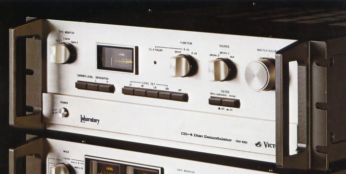
A CD-4 demodulator of the Laboratory 1000 series specially developed for professional use such as studios.
The Laboratory 1000 Series was designed and manufactured by selected staff members of the Victor Laboratory Center. The characteristics of the Series are compensated by the measured data of all the machines, and the specifications can be changed slightly according to the purpose.
In addition to using highly reliable parts for all parts, it is checked up to one resistance and one knob.
It is equipped with an automatic noise reduction circuit ANRS in order to improve the S / N ratio by suppressing mid - and high-frequency noise generated from the record in the CD-4 system.
In addition, the ANRS ON/OFF switch is mounted on the rear panel so that the entire ANRS circuit can be lost.
The rear panel has a DET BAND CONTROL switch.
When this switch is in the Auto position, the demodulation detection band of the sub-channel is automatically changed according to the input, and high-blend operation is added to maintain noise-free and stable operation.
When the switch is in the Fix position, these actions are not performed and it is fixed to the maximum lock range. Therefore, it can be used for noise checking of records or listening test of cartridges.
The CD-4 recording circuit is designed to delay the main channel by 40 μ s in order to compensate for the delay time of the sub channel caused by the cartridge and demodulator during demodulation. In addition, the CD4-1000 takes into consideration the variation in the delay characteristics of the cartridge, and the delay time can be finely selected within ± 25 μ s with an 11-step switch. The channel separation of 30 dB or more can be obtained in the record operation state.
In addition, it is equipped with a cross-modulation reduction circuit that reduces distortion caused by crosstalk in the cartridge, a demodulation circuit using a High Legh near PLL circuit that is a mixture of ICs and discrete devices, and an ANRS circuit that is completely symmetrical with the recording system. It pursues low distortion rate, high S/N and high separation.
All of these circuits are plug-in units, and the structure of maintenance is excellent.
The RIAA equalizer circuit uses a ± 2 power supply differential input Darlington class A operation circuit.
In addition, the cartridge load resistance change-over switch is mounted on the rear panel, and the input resistance of Phono1 and 2 can be changed independently.
It uses a 4-strand master trimming volume that combines the advantages of volume and attenuator.
This volume is the same as the JP-V1000 model.
The CD4-1000 is equipped with two pre-set circuits that can adjust the separation level, the delay time of the sum signal band, and the channel level of each of the two types of cartridges.
In addition to using 4ch/2ch by switching the function selector, it is also possible to bypass the entire demodulator circuit and send the input directly.
Equipped with a level check meter, the carrier level, separation, 4 ch level balance, etc. can be accurately adjusted by the signal from the attached test record.
This meter is a high-precision vertical type meter similar to JP-V1000.
Equipped with a subsonic filter and noise filter.
The noise filter is a high-cut filter that works only on sub-channels. It effectively cuts noise while reducing the effect of frequency response on audio output.
A cast-aluminum side frame is used to increase the rigidity of the body and achieve stable rack-mounting.
The mount size is BTS standard and can be changed to RCA type by order.
The power supply is a universal system of 100 V, 117 V, 220 V and 240 V. It can be used overseas simply by changing internal connections.
.JPG)
.JPG)
.JPG)
Model Rating
| Type | CD-4 dimodulator | ||||
| Channel separation |
|
||||
| Total harmonic distortion factor | 0.03% (Input 2 mv, 1 khz) | ||||
| Frequency characteristic | 20 Hz to 20 kHz | ||||
| Residual noise | 1.2 μ V (Input Conversion) | ||||
| Input level | 1 mv ~ 7 mv (1 khz) 1 mv ~ 7 mv (30 khz) |
||||
| Input impedance | 100k Ω, 47k Ω switching | ||||
| Output level | 300 mv (at Volume max) | ||||
| Output impedance | 1k Ω or less | ||||
| Equalizer | RIAA deviation ± 0.3 dB | ||||
| Filter | Subsonic : 18 Hz, -3dB Noise (subchannel only) : 10 kHz, -6dB |
||||
| Deviation from ANRS standard | + / - 0.2 dB (-10VU) + / - 0.5 dB (0, -20VU) |
||||
| Semiconductor used | Transistor : 130 units IC : 10 FET : 9 Diode : 26 Units |
||||
| Power consumption | 35W (Electrical Appliance and Material Control Law) | ||||
| External dimensions | Width 478x Height 162.5x Depth 488 mm | ||||
| Weight | 15.0kg | ||||
| Attachment | Record for reconciliation | ||||
| Sold Separately | System Rack LUC-1000M (Built to Order) |