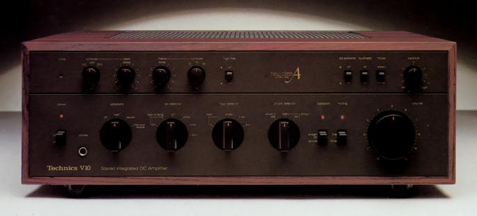
Technics SU-V10
¥ 198,000 (around 1979)
Commentary
An integrated DC amplifier that uses Technics' new classA circuit.
The new classA circuit was developed as a circuit having only the excellent points of classA operation and class B operation, and it is realized by a synchronous bias circuit.
This synchronous bias circuit controls the bias of the output stage in synchronization with the input signal. It has a structure in which a constant bias current is supplied to the - side output stage when the + side signal is being reproduced, and to the + side output stage when the - side signal is being reproduced. In this structure, a constant bias current is supplied to the + side output stage when the - side signal is being reproduced. Therefore, the transistor of the output stage is always active regardless of the presence or absence of the signal and switching distortion does not occur.
The circuit of SU-V10 consists of an initial stage composed of FET differential circuit and cascode circuit, a voltage amplifier stage with constant current load, a voltage driver circuit for emitter-follower output with A-class operation up to SEPP connected transistors, and a Darlington connected SEPP output stage through a synchronous bias circuit.
A straight DC method is adopted in which a capacitor with a time constant is eliminated from the stage between the high-level input and the output terminal of the speaker and negative feedback (NFB). This realizes faithful waveform transmission over the entire audible band from ultra-low band (direct current).
In order to suppress DC drift, which is the biggest problem of DC amplifier, the characteristics of the pair elements such as differential and current mirror are precisely matched, and the active thermal servo circuit is mounted.
This circuit is designed to compensate for the drift factor itself by actively compensating for the imbalance in the temperature characteristics between elements. The circuit integrates the signal output with an operational amplifier with excellent linearity and accuracy, and drives a heat-generating transistor that is thermally coupled with the signal transistor. The heat-coupled transistor has only a case bonded to it and is electrically isolated from the signal transistor, so there is no adverse effect on the signal.
This circuit realizes a high DC stability of 0 ± 5 mv or less under a wide temperature range of -10 ℃ to 50 ℃.
The power transistor uses SLPT, which is equivalent to 200 built-in small-signal transistors with excellent high-frequency characteristics. It realizes a high-frequency reproduction limit of 100 MHz order and an extremely linear amplification factor from small current to large current.
It uses a plugged power block.
In this method, large signal and large current components such as electrolytic capacitors, drive circuits, and power transistors are compactly concentrated in an integrated radiator block, reducing the problem of circuit configuration that deteriorates high frequency characteristics such as electromagnetic induction.
A large capacity transformer with a margin is used for the power transformer.
By floating the coil in a special resin and storing it in a case with a high shielding effect, this transformer minimizes leakage flux combined with the effect of a surplus electric power capacity.
The phono equalizer circuit has an ICl configuration in which a low-noise dual FET is arranged as a differential amplifier at the first stage and a coupling capacitor at the input stage is eliminated.
Equipped with MC pre-preamp.
Equipped with an independent input/rec selector.
A remote action switch is adopted to realize straight circuit wiring without deterioration of characteristics.
Equipped with a mid-point defeat tone control that provides a flat frequency response at the mid-point.
It is equipped with a protection circuit using a relay that also works as a muting when the power is turned on/off.
The electrolytic capacitor mounted on the Concentrated Power Block uses a low-impedance super audio capacitor to reduce electromagnetic radiation from the electrolytic capacitor.
Model Rating
| Type | Integrated DC amplifier |
| Effective power | 160W + 160W (4 ω, 20 Hz-20 kHz, 0.007%) 120W + 120W (8 ω, 20 Hz-20 kHz, 0.003%) 120W + 120W (8 ohm, 1 khz, 0.0003%) |
| Output Bandwidth (THD 0.01%) | 5 Hz to 100 kHz |
| TIM | Cannot be measured with the Sparena. |
| Frequency characteristic | Straight DC : DC ~ 20 khz + 0 -0.1 db DC ~ 200 khz + 0 -3dB Via tone : 2 Hz to 150 kHz + 0 -3dB |
| Signal-to-noise ratio (IHF, 98A) | straight DC:110dB |
| Residual noise | 300 μ V |
| Damping factor | 100 (8 Ω) |
| Load impedance | Main or Remote : 4 Ω ~ 16 Ω Main + Remote : 8 Ω ~ 16 Ω |
| Input Sensitivity / Impedance | Phono1, 2 mm : 2.5mV/47k Ω Phono1 MC : 100 μ V/47 Ω Tuner, Aux, Tape : 200mV/47k Ω Main in : 1V/18k Ω |
| Phono maximum allowable input (1 kHz, RMS) | Phono MM:250mV Phono MC:10mV |
| Pre-part total harmonic distortion factor (20 Hz to 20 kHz) | Phono MM → Rec out : 0.0015% (at 5 v output) Phono MC → Rec out : 0.005% (at 5 v output) Tuner, Aux → Pre out (via tone) : 0.005% at 1 v output |
| Phono signal-to-noise ratio (IHF-A) | Phono MM:90dB Phono MC (250 μ V) : 80 dB Phono MC (100 μ V) : 72 dB |
| Phono frequency characteristics | 20 Hz to 20 kHz, RIAA standard curve ± 0.15 dB |
| Tone control | Bass : ± 7.5 dB (50 Hz, turnover 500 Hz) Treble : ± 7.5 dB (20 kHz, 2 kHz turnover) |
| Turnover frequency | Bass : 125 Hz, 250 Hz, 500 Hz Treble : 2 kHz, 4 kHz, 8 kHz |
| Filter | EQ subsonic : 20 Hz, -12dB/oct. High : 7 kHz, -6dB/oct. |
| Loudness control | + 7 dB (100 Hz, Volume -30dB) |
| Muting | -20dB |
| Output voltage | Pre-out (rated) : 1 V Pre out (maximum) : 7 V Rec out:200mV |
| Pwer | 100 VAC, 50Hz/60Hz |
| Power consumption | 300W |
| External dimensions | Width 471x Height 172x Depth 420 mm |
| Weight | 23.0kg |