Technics SE-A3
¥ 300,000 (released in December 1979)
Commentary
This is a stereo power amplifier that is at the top of Technics's new class A amplifier that eliminates switching distortion and crossover distortion.
It uses a new classA amplifier using a synchronous bias circuit unique to Technics.
The synchronous bias circuit detects the positive and negative cycles of the signal prior to the output stage and always applies a constant bias to the output transistor whose amplification is stopped to prevent the occurrence of switching distortion. In addition, since the signal path and the bias current are independent, the output transistor always maintains an appropriate operating point.
Furthermore, since the fast response diode switching between the positive and negative half-cycle has characteristics close to the ideal square characteristic, the new classA as a whole shows that the rise and fall waveforms of the current are very close to the ideal square characteristic, and the resultant transfer characteristic becomes a straight line near the 0 cross point. This eliminates the problem of crossover distortion.
The DC amplifier configuration does not include any capacitors in the signal path from input to output and in the feedback loop to obtain excellent transmission characteristics.
The first stage of the circuit consists of one chip dual FET differential amplifier with uniform temperature characteristics, bootstrap cascode and current mirror load. DC drift, which is a problem in DC amplifier, is ± 10 mv or less at -10 ℃ to + 50 ℃ by the adoption of dual FET.
In the SE-A3, this first stage is followed by a differential amplified double cascode, a voltage amplification stage of a current mirror load, a 2-stage class A SEPP driver stage, a synchronous bias circuit, a PP driver of SLPT2 module, and an output stage of DLPT4 module.
By integrating the power supply with the output stage that handles large large current, we have adopted an insulated power block that prevents electromagnetic induction, thereby greatly reducing high-frequency distortion.
The newly developed DLPT (dual linear power transistor) is used as the output transistor.
DLPT is a high fTSLPT (Super Linear Power Transistor) of NPN and PNP is made into a twin structure in which two SLPT (Super Linear Power Transistor) of NPN and PNP are made into one pack. Not only are the characteristics of the pair transistors well aligned, large heat capacity is realized, and stable high output is possible.
In addition, because the structure is symmetrical and the emitter resistance is not dispersed, the current waveform taken out from the power block is finally the same as that of the class A operation, which greatly improves the high-frequency characteristics.
The electrolytic capacitor is equipped with two newly developed low-impedance super audio capacitors (capacity 22,000 μ F) per channel, for a total of four capacitors.
This capacitor consists of four flat low-inductance capacitors connected in parallel and sealed in a resin case. Compared with conventional capacitors, this capacitor achieves an impedance improvement of 7 dB in the mid-range and 12 dB at 1 MHz.
All metal film resistors selected by strain selection are used for all resistors to achieve low noise and low strain as well as high reliability.
A 3-layer bus line is used for the output line and the positive and negative power supply lines, which handle large currents, to minimize loops caused by electromagnetic induction.
Using two power transformers in the power supply section, the left and right sides are completely independent monaural construction, eliminating interference between the left and right channels that occurs through the power supply section.
In addition, a constant voltage power supply with a constant current buffer is applied to the voltage amplification stage to eliminate noise.
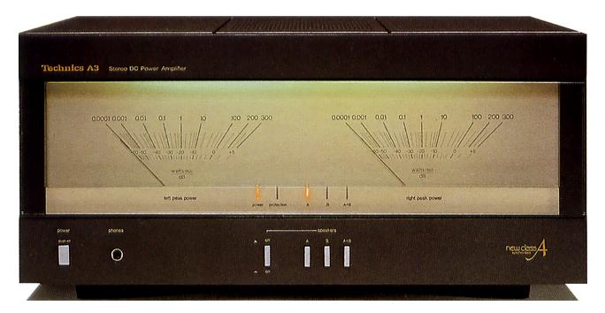
Equipped with a large and high-precision peak power meter.
This meter can read directly from 0.0001W to the pulse width without changing the meter range. It also has an attack time of 50 μ s and follows a single 20 kHz sine wave for accurate power display.
Equipped with two types of speaker terminals.
It is equipped with a relay protection circuit. If a DC output appears at the speaker terminal, the relay functions to protect the speaker. The relay also functions to protect the amplifier against a short circuit at the speaker terminal.
These actions can be confirmed by indicators and automatically reset when the cause is removed.
.JPG)
.JPG)
Model Rating
| Type | Stereo DC power amplifier |
| Effective power | 320W + 320W (4 ω, 20 Hz-20 kHz, 0.003%) 200W + 200W (8 ω, 20 Hz-20 kHz, 0.002%) 220W + 220W (8 ohm, 1 khz, 0.001%) |
| Total harmonic distortion factor | 0.001% (at 20 Hz to 20 kHz, Rated Output -3dB) |
| TIM Distortion | Unmeasurable |
| Output bandwidth | 5 Hz ~ 100 kHz (T. H. D. 0.007%) |
| Frequency characteristic | DC ~ 20 khz + 0 -0.1 db DC ~ 300 khz + 0 -3dB |
| Signal-to-noise ratio (IHF-A) | 123dB |
| Residual noise | 150 μ V |
| Damping factor | 120 (8 Ω) |
| Load impedance | Main or remote : 4 Ω ~ 16 Ω Main and remote : 8 Ω ~ 16 Ω |
| Input Sensitivity / Impedance | 1V/47k Ω |
| Meter Characteristics | |
| Indication range | 0.0001W ~ 300W (8 Ω) -60dB to + 5 dB |
| Frequency characteristics (indication accuracy) | 10 Hz to 10 kHz ± 1 dB (less than -40dB) 10 Hz to 20 kHz ± 1 dB (-40dB or more) |
| Attack time | 50 μ sec |
| Recovery time | 750 msec (0 dB → -20dB) |
| <General> | |
| Pwer | 100 VAC, 50Hz/60Hz |
| Power consumption | 560W |
| External dimensions | Width 430x Height 208x Depth 507 mm |
| Weight | 35.2kg |