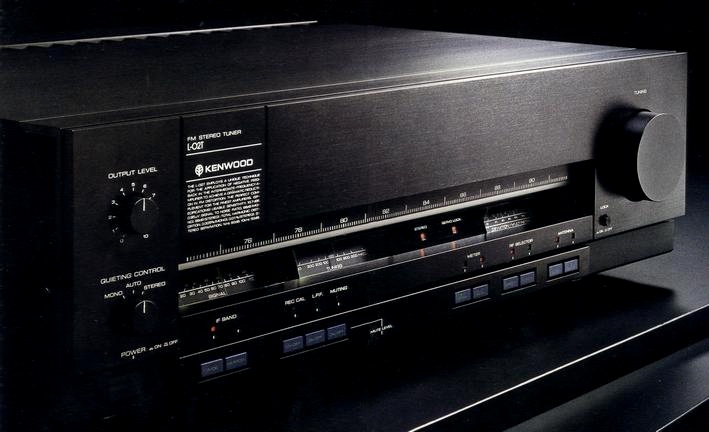
KENWOOD L-02T
¥ 300,000 (around 1982)
Commentary
Based on the development theme of the world's lowest distortion rate and high signal-to-noise ratio, we have developed a high-end FM stereo tuner that achieves both reception and audio characteristics, which have been a problem for many years, through new technologies such as a non-spectrum IF system and a non-step sample-and-hold MPX.
The newly developed non-spectral IF system removes the FM spectrum from the signal entering the IF, passes through an IF filter to remove the interfering signal, and then returns it to the original FM signal for detection. This realizes low distortion while maintaining high selectivity even in the WIDE band.
The principle of FM broadcasting is to use frequency modulation, which changes the carrier frequency according to the audio signal. The modulated FM signal transmits information as a spectrum whose bandwidth and level always changes according to the strength and frequency components of the audio signal. However, the FM tuner uses an IF bandpass filter to obtain selectivity characteristics in order to receive only the desired station. At this time, the conventional IF system passes the FM signal with this spectrum through the IF bandpass filter as it is, so it generates a considerable level of distortion. The non-spectrum IF system passes the signal with the FM spectrum removed through the IF bandpass filter, so it generates almost no distortion while maintaining excellent interference rejection capability.
The circuit operates in such a way that the VCO (voltage controlled oscillator) oscillates a 6.2 MHz signal with exactly the same shift as the received FM broadcast, and the first mixer (subtraction mixer) eliminates the FM shift of the FM signal so that "input signal -VCO oscillation signal = non-spectrum IF signal". Therefore, the non-spectrum signal without FM shift passes through the band-pass filter, ensuring sufficient selectivity characteristics without causing distortion. Then, the second mixer (addition mixer) adds the VCO signal with FM shift again, and it is guided to the demodulation circuit.
Based on the Sample-and-Hold MPX, it is equipped with the Non-Step Sample-and-Hold MPX, which is more complete and has succeeded in improving phase characteristics and reducing distortion.
In conventional sample-and-hold MPX, a low-pass filter was used to cancel out the 38 kHz subcarrier component from the demodulated output. However, the 38 kHz frequency is close to the upper limit of the audio band of 20 kHz, so even a well-designed filter affects sound quality and characteristics.
To solve this problem, the Non-Step Sample-And-Hold MPX employs a method of eliminating the 38 khz subcarrier component by combining, synthesizing, and integrating waveforms. The demodulation output is the audio signal itself, so a low-pass filter is not necessary for practical use.
In addition, the L-02T employs a low-pass filter ON-OFF switch, which allows the use of a low-pass filter for special applications such as measurement. The carrier leak when the low-pass filter is ON is suppressed to approximately 70 dB.
A direct conversion system is adopted in which the input signal is directly input to the mixer stage without passing through the RF amplifier.
The direct conversion system consists of triple tuning, a mixer and two stages of IF amplifier. The mixer is a balanced type using pair-selected J-FET, and the IF amplifier at the latter stage is a push-pull amplifier using the same FET to ensure a wide dynamic range and suppress IM distortion at the IF stage.
Direct Position reception is available in areas where the S-meter shows 60 dBf or more.
Uses an RF selector.
It can be used in the direct conversion position when there is sufficient input power or when there is a large power station close to it, or in the high-sensitivity normal position when the input power is small. The normal position consists of a high-frequency linear high-precision 7 series varicon with a wide air gap composed of a single-single-triple tune.
The RF amplifier uses a DD-MOS type FET with a large power gain and wide dynamic range, and a J-FET with a high Gm with greatly reduced third intermodulation distortion. In addition, the output of the third stage of the triple tune is connected to the next stage (balanced mixer) with low impedance. This design takes impedance matching into consideration. The local oscillator circuit and the varicon are integrated, the scale accuracy is improved according to the rotation angle of the varicon, and frequency drift due to changes in temperature and humidity is minimized by using three dimensional wiring as a block.
In order to ensure a wide dynamic range even in normal position, a front-end IF and AGC are mounted.
This circuit works only for large inputs, such as clipping, and suppresses distortion during normal position.
All the front-end IF stages after the mixer are push-pull so that excellent dynamic range can be obtained.
The power supply section is further developed from the concept of power separation of the local oscillator circuit adopted in the L-01T, and is equipped with an independent power supply for each operation stage. Therefore, the power transformer is composed of two transformers with six windings.
Since the front end is an independent power supply, there is no influence from the power supply from other stages. In addition, there are three power supplies for the MPX section, and after the left and right are separated, there are two completely independent power supplies.
The signal meter circuit consists of a dedicated IF amplifier circuit and a logarithmic amplifier.
The maximum scale is 110 dBf in proportion to the antenna input, and it can be used as an electric field strength meter. It can know the accurate input power with the equal interval scale.
An adjuster that can move the dial scale plate by 2 mm to the left and right is installed for more precise tuning operation.
Equipped with two switching type antenna terminals.
A Σ drive circuit is mounted on the output.
The primary side of the tuner and preamp transformer is connected by an AC cord, and the secondary side is connected by an electrostatic or electromagnetic coupling in an AC manner. This creates a large loop between the tuner and the preamp and causes a distorted current to flow through the preamp due to the mutual power supply.
In order to solve this problem, the L-02T uses the Σ drive method for its output. Since a single ground cable acts as a bypass for the distortion current, even if a high-impedance cable is used, only the undistorted signal voltage can be transmitted to the preamplifier, and the high-quality sound obtained by the new IF circuit or MPX circuit can be transmitted to the input terminal of the preamplifier.
.jpg)
.JPG)
Model Rating
| Type | FM stereo tuner | |||||||||||||||||||||||||||||||||
| Receiving frequency range | 76 MHz to 90 MHz | |||||||||||||||||||||||||||||||||
| Antenna impedance | Systems A and B2 : 75 Ω unbalanced | |||||||||||||||||||||||||||||||||
| Sensitivity (75 Ω) | Normal : 10.7 dBf (new IHF) / 0.95 μ V (IHF) Direct : 25.2 dBf (new IHF) / 5.0 μ V (IHF) |
|||||||||||||||||||||||||||||||||
| SN ratio 50 dB sensitivity |
|
|||||||||||||||||||||||||||||||||
| Harmonic distortion factor (ANT in → Σ out, 85 dBf input) |
|
|||||||||||||||||||||||||||||||||
| SN ratio (ANT in → Σ out, 100% modulation, 85 dBf input) | mono:98dB stereo:88dB |
|||||||||||||||||||||||||||||||||
| Capture ratio | wide:0.9dB narrow:2.5dB |
|||||||||||||||||||||||||||||||||
| Effective selectivity (IHF) | wide:45dB Narrow : 65 dB (± 300 kHz) |
|||||||||||||||||||||||||||||||||
| Stereo Separation (ANT in → Σ out) |
|
|||||||||||||||||||||||||||||||||
| Frequency Response (ANT in → Σ out) | 15 Hz to 15 kHz + 0. 2-0. 5 dB | |||||||||||||||||||||||||||||||||
| Image interference ratio (84 MHz) | normal:120dB | |||||||||||||||||||||||||||||||||
| IF Interference Ratio (84 MHz) | normal:120dB | |||||||||||||||||||||||||||||||||
| Spurious interference ratio (84 MHz) | normal:120dB | |||||||||||||||||||||||||||||||||
| AM suppression ratio | 70dB | |||||||||||||||||||||||||||||||||
| Subcarrier suppression ratio | Low-pass filter on : 70 dB Low-pass filter off : 65 dB |
|||||||||||||||||||||||||||||||||
| Rec calibration | 440 Hz (50% modulation) | |||||||||||||||||||||||||||||||||
| Output Level / Impedance (1 kHz, 100% modulation) | Fixed output : 0.75V/1 Ω or less Σ output (variable) : 1.5V/1 Ω or less |
|||||||||||||||||||||||||||||||||
| Multipath output | Vertical Output : 0.5V/3k Ω Horizontal output : 0.01V/10k Ω |
|||||||||||||||||||||||||||||||||
| Dial Scale Adjuster | + / - 2 mm | |||||||||||||||||||||||||||||||||
| Power supply voltage | 100 VAC, 50Hz/60Hz | |||||||||||||||||||||||||||||||||
| Rated power consumption (Electrical Appliance and Material Control Law) | 28W | |||||||||||||||||||||||||||||||||
| Maximum external dimensions | Width 480x Height 147.5x Depth 423 mm | |||||||||||||||||||||||||||||||||
| Weight | 12.4kg |
.jpg)
.jpg)