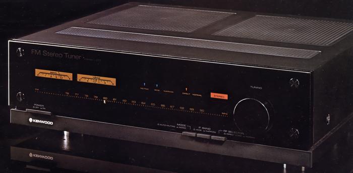
KENWOOD L-01T
¥ 160,000 (around 1979)
Commentary
This FM stereo tuner is based on excellent circuit technologies such as pulse counting and sample-and-hold MPX, and pursues non-magnetic materials.
The L-01T is the first tuner to use a non-magnetic housing.
The non-magnetic material used is almost the same as L-01A. The sub panel and back panel are made of new reinforced nylon with excellent impact resistance and durability, the side frame is made of aluminum case, and the bottom plate is made of wood.
In addition, 99.96% pure oxygen-free copper is used for structural material and bus-earth bar, and smoked acrylic is used for front panel.
An independent power source oscillator is installed to prevent deterioration of sound quality through the power source.
The detection circuit and MPX circuit generate an audio signal on the + B line by means of the output impedance between the + B power supply and ground. The signal component generated at + B is fed back to the local oscillator circuit via the power supply, and the frequency of the local oscillator circuit is modulated by FM to become a noise component, which appears in the output.
The L-01T employs an independent power source oscillator in which the power source of the local oscillator circuit is separated from the power source of the detector and MPX circuit. This prevents feedback of the signal through the power source from the detector circuit and MPX circuit, and realizes a clear FM signal.
It employs a direct conversion system in which the input signal is directly input to the mixer stage without passing through the RF amplifier to obtain excellent two signal characteristics and a wide dynamic range.
The direct conversion system consists of a triple tuning, a mixer and two stages of IF amplifier. The mixer is a balanced type using a pair selected dual J-FET. The IF amplifier in the latter stage is a push-pull amplifier using the same FET. This ensures a wide dynamic range and suppresses IM distortion at the IF stage.
Equipped with an RF-selector, it can be used in the direct conversion position when there is sufficient input or when there is a large power station close to it, and in the high sensitivity normal position when the input is small.
The normal position consists of a frequency-linear high-precision 7-series varicon with a wide air gap and a single-single-triple tune. The RF-amplifier uses a DD-MOS type FET with a large power gain and a wide dynamic range and a J-FET with a high Gm with a greatly reduced third intermodulation distortion. The output of the third stage of the triple tune is connected to the next stage (balanced mixer) with a low impedance. This design takes impedance matching into consideration.
In addition, the local oscillator circuit and the varicon are integrated to improve the accuracy of the scale according to the rotation angle of the varicon. In addition, it is blocked by three dimensional wiring to suppress frequency drift due to changes in temperature and humidity.
The detection section employs a pulse count method with further improvements in the waveform shaping section and drift countermeasures.
Since the entire detection range over a wide band is straight, this method can reproduce the broadcast station's music waveform as it is as an output waveform, and is an excellent method without causing distortion in principle.
In order to maximize the advantages of the pulse count detection method, a double conversion method is adopted.
In this method, the intermediate frequency of 10.7 MHz obtained by the first IF is further converted to the second IF of 1.96 MHz. As a result, the relative frequency shift can be increased, so that the broad linear width obtained by pulse count detection can be fully utilized, and the SN ratio is greatly improved by increasing the detection efficiency.
Using the sample-and-hold MPX circuit developed in KT 9900, the separation has been greatly improved.
Since only the peak is sampled and held, there is little change in the amplitude of the 38 kHz component when modulation is applied, and dynamic carrier leakage due to changes in the modulation level of voice hardly occurs. Together with the pilot canceler, the frequency characteristics of the low-pass filter in the final stage are greatly improved.
Uses synchronized touch tuning system.
After tuning to the broadcasting station with the tuning knob, the lights of the signal meter and tuning meter turn off after about 2 seconds when you release your finger. During listening, only the tuning point of the dial scale, operation indicator and stereo indicator light. In addition, since the servo lock is built in, once tuning is done, there is no fear of mistuning.
In addition, when you want to always look directly at the meter or dial scale, it can be switched with the back switch.
A clean subcarrier system and a pilot canceler are installed in the MPX section.
The clean subcarrier system prevents the audio signal from mixing into the switching signal, allowing the pilot canceler to operate correctly without beat distortion.
The low-output impedance design takes advantage of the know-how acquired through the direct drive amplifier system, which is the original form of the separate amplifier completed by Trio.
This reduces the effect of the input capacity of the connected shield wire and amplifier on sound quality.
The power supply unit is 20 VA for the local oscillator circuit side and 24 VA for the other RF amplifier circuit, detection circuit and MPX circuit side. An extremely large transformer is used as the transformer of the tuner to constitute two power supplies.
14 v for the signal system of the front-end IF section, ± 16 v for the low-frequency amplifier circuit of the MPX, and + 12 v for the local oscillator circuit. Constant voltage power supplies are installed for each block after rectification to reduce interference between each block. Large-capacity electrolytic capacitors of 2,200 μ F at the + 14 v outlet, 1,000 μ Fx2 for ± 16 v, and 220 μ F for + 12 v are installed.
.JPG)
.JPG)
Model Rating
| Type | FM stereo tuner | ||||||||
| Receiving frequency range | 76 MHz to 90 MHz | ||||||||
| Antenna impedance | 75 Ω unbalance | ||||||||
| Sensitivity (75 Ω) | Normal : 10.3 dBf (new IHF) / 0.9 μ V (IHF) Direct : 20.7 dBf (new IHF) / 3 μ V (IHF) |
||||||||
| SN ratio 50 dB sensitivity |
|
||||||||
| Harmonic distortion factor |
|
||||||||
| SN ratio (100% modulation) | mono:86dB stereo:80dB |
||||||||
| Image interference ratio | 120dB | ||||||||
| Selectivity (IHF) | wide:45dB narrow:65dB(300kHz) |
||||||||
| IF interference ratio | 120dB | ||||||||
| Spurious interference ratio | 120dB | ||||||||
| AM suppression ratio | 65dB | ||||||||
| Capture ratio | wide:0.9dB narrow:2.5dB |
||||||||
| Subcarrier suppression ratio | 70dB | ||||||||
| Stereo separation |
|
||||||||
| Frequency characteristic | 15 Hz to 15 kHz ± 0.5 dB | ||||||||
| Output Level / Impedance |
|
||||||||
| Power supply voltage | 100 VAC, 50Hz/60Hz | ||||||||
| Rated power consumption | 50W (Electrical Appliance and Material Control Law) | ||||||||
| Maximum external dimensions | Width 440x Height 136x Depth 452 mm | ||||||||
| Weight | 9.1kg |