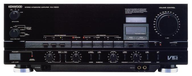
KENWOOD KA-1100D
¥ 129,000 (around 1986)
Commentary
A pre-main amplifier that uses Super DLD (Dynamic Linear Drive) circuit.
New VIG circuit is installed in order to realize linear signal transfer.
The bootstrap of the output transistor is connected to the base of the final transistor and a buffer is inserted. By keeping the voltage of the final transistor constant, the bare characteristics of the power amplifier stage before applying negative feedback are improved, and the signal transfer between the A class stage and the B class stage is made more accurate.
A DLD circuit is used to drive the speakers with higher quality signals.
The DLD circuit consists of two high-power and low-power amplifiers at the output, and a power supply circuit that supplies powerful energy to speakers by combining these amplifiers with a dedicated power supply.
As a result, excellent power supply capability is demonstrated, and the peak signal of CD, which is said to be 100 times the average signal, is reproduced in pure.
The low-power amplifier can handle up to approximately 50W, and the low-distortion low-level amplifier processes most of the music signal, providing excellent expressive power.
Moreover, since this low-power amplifier is driven by a huge power supply that can output more than 300W, the impedance of the power supply is reduced and high quality that is not affected by load fluctuations is obtained.
The power supply section uses a large core and a large transformer with increased lamination to increase heat radiation effect and low winding impedance. The block Chemicon uses four 15,000 μ F dedicated Chemicon for DLD.
In addition, the equalizer is equipped with a dedicated winding and the power amplifier is equipped with a stabilizing power supply except for the power amplifier stage.
On the circuit side, the output transistor is configured in a discrete configuration to expand the regenerative bandwidth characteristics and current supply capability, so that energy from the power supply can be utilized.
A Σ drive is used to suppress distortion when mounting speakers.
By connecting the NF loop to the speaker terminal and inserting parts that cause distortion and sound quality degradation into the NF loop, the performance at the output terminal of the amplifier is improved.
In addition, all GND lines are concentrated at one point on the speaker terminal of the amplifier to suppress the increase of mutual interference caused by GND line patterns and wires.
The EQ section is an improved version of the dual-head EQ amplifier and employs a dual EQ system in which each MC/MM has its own EQ amplifier.
The equalizer amplifier for MM has an FET input with Hi-Gm = 40 ms ultra-low noise, and the equalizer amplifier for MC has a transistor input with γ' bb = 4 π ultra-low noise. Each of them can independently perform their functions and achieve a distortion factor of the measurement limit level.
In order to reduce the occurrence of crosstalk, the wiring of wires is eliminated, each printed circuit board is separated, and a simple construction according to the signal flow is adopted to reduce interference between components.
In addition, a thorough vibration analysis has been introduced into the housing design, and unlike conventional integrated chassis, which tend to cause natural vibration of the housing, it has a unique multi-frame structure with a frame attached to each block for increased strength.
Uses a soft / hard 2-layer type insulator that suppresses vibration transmission.
Gold plated pin jacks are used for all Phono and line input systems.
It is equipped with Dual Lec Selector with enhanced dubbing function and Winking Power Indicator with protection operation display function.
Equipped with tone control and loudness control.
Model Rating
| Type | NEW VIG / DLD Integrated Amplifier | ||||
| Rated Output (Both Channel Operation) |
|
||||
| Total harmonic distortion rate (20 Hz to 20 kHz) |
|
||||
| Intermodulation distortion factor (60 hz : 7 khz = 4 : 1) | CDs, Tuenr, AUX, Tape → SP terminals : 0.003% (8 Ω at rated output) | ||||
| Frequency characteristic | CD, Tuner, AUX, Tape → SP connector : DC ~ 200 khz + 0 -3dB (1 hz ~ 150 khz) | ||||
| Damping factor (50 Hz) | 1000 | ||||
| Input Sensitivity / Impedance | Phono MM : 2.5mV/47k Ω Phono MC : 0.1mV/100 Ω CD, Tuner, AUX, Tape : 150mV/47k Ω Adaptor In : 150mV/47k Ω |
||||
| Signal-to-noise ratio (IHF-A) | Phono MM → SP Terminal : 78 dB (EIAJ), 87 dB (Input Short CP-301) Phono MC → SP Terminal : 78 dB (EIAJ), 76 dB (250 μ V) (Input Short CP-301) CD, Tuner, AUX, Tape → SP terminal : 80 dB (EIAJ), 110 dB (input short CP-301) |
||||
| Tone control |
|
||||
| Loudness control | 30Hz/90Hz : 0 to + 8 dB (Volume-30dB) | ||||
| Subsonic filter (-3dB) | 18 Hz, 6dB/oct. | ||||
| Output bandwidth (0.04% distortion factor) | CD, Tuner, AUX, Tape → SP connector : 5 Hz to 50 kHz | ||||
| Phono maximum allowable input (1 kHz, THD 0.003%) |
Phono MM:210mV Phono MC:8mV |
||||
| Phono RIAA deviation (20 Hz to 20 kHz) | + / - 0.2 dB | ||||
| Output Level / Impedance | Pre Out : 2V/600 Ω Tape Rec : 150mV/220 Ω |
||||
| Pwer | 100 VAC, 50Hz/60Hz | ||||
| Rated power consumption (Electrical Appliance and Material Control Law) | 410W | ||||
| Power outlet | Power switch interlock : 2 systems, 100W Power switch not linked : 1 system, 400W |
||||
| External dimensions | Width 440x Height 170x Depth 420 mm | ||||
| Weight | 18kg |