SONY ST-5150
¥ 39,800 (released in 1973)
Commentary
ES series FM/AM tuner.
For the front end, a newly developed jation FET and four variable capacitor are used for the high-frequency amplifier circuit, and a stable local oscillator circuit and FET mixer circuit are also used.
This enables stable reception even in high-electric-field regions.
A 2-element solid-state filter is used in the intermediate frequency amplifier circuit and a high-performance IC is used in the IF section in order to receive the sound quality as it is sent from the receiving station.
The MPX circuit that separates stereo signals employs a high-integration IC and a newly developed coil unit exclusively for the IC to improve stereo separation.
In addition, since it is a non-adjustment type sealed unit, there is no worry of adjustment slippage and it is not affected by heat and humidity.
The AM section uses a triple-tuned IFT, which includes a high-integration IC solid-state filter. The design is strong against strong electric fields and has excellent interference rejection capability.
In addition, in order to cope with the unpleasant high-frequency noise that occurs when listening to AM broadcasting at night with a Hi-Fi tuner, we have solved this problem by adopting an input circuit that shuts out unnecessary input signals and a highly selective IF circuit.
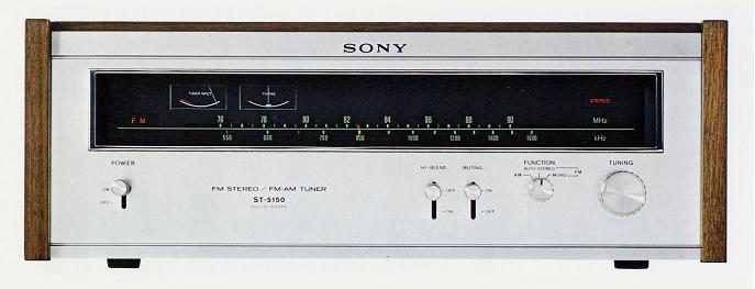
It uses an input meter that shows the strength and weakness of radio waves and a tuning meter of the center 0, and the dial indicator is fluorescent.
Equipped with a green edge light, a large dial with an effective running width of 180 mm and evenly spaced graduations are used.
A FET switch is used for the muting circuit.
The use of a low-pass filter allows recording without carrier leak or beat (high-sound interference noise) during tape recording.
Input terminal and connector for coaxial cable are included for easy installation of 75 Ω coaxial cable which is advantageous for noise.
It is equipped with an output terminal that can observe multipath phenomena, and by connecting it to an oscilloscope, the best antenna installation position and direction can be obtained.
.JPG)
Model Rating
| Type | FM/AM Tuner | ||
| Circuit system | Superheterodyne system | ||
| FM Tuner Section | |||
| Antenna terminal | 300 Ω Balanced Type 75 Ω unbalanced type (coaxial cable connector) |
||
| Receiving frequency | 76 MHz to 90 MHz | ||
| Intermediate frequency | 10.7MHz | ||
| Practical sensitivity | 2.0 μ V (IHF) | ||
| Sensitivity | 1.6 μ V (S/N = 30 db) | ||
| Signal-to-noise ratio | 70dB | ||
| Capture ratio | 1.0dB | ||
| Selectivity | 70dB(IHF) | ||
| Image interference ratio | 75dB | ||
| IF interference ratio | 90dB | ||
| Spurious interference ratio | 90dB | ||
| AM suppression ratio | 56dB(IHF) | ||
| Frequency characteristic | 20 Hz to 15 kHz, ± 1.0 dB | ||
| Distortion factor | Mono : 0.3% at 400 Hz, 100% modulation Stereo : 0.5% at 400 Hz, 100% modulation |
||
| FM stereo separation | 40 dB or More (400 Hz) | ||
| 19 khz and 38 khz suppression ratio | 50dB | ||
| Output Voltage / Impedance | Fixed output : 750mV/10k Ω (at 100% modulation) Variable output (Variable) : 0 ~ 2V/1.8k Ω (at 100% modulation at maximum output)
|
||
| <AM Tuner Section> | |||
| Antenna | Ferrite bar antenna With External Antenna Terminal |
||
| Receiving frequency | 530 kHz to 1,605 kHz | ||
| Intermediate frequency | 455kHz | ||
| Sensitivity | 50dB/m (when bar antenna is used) 30 μ V (when external antenna is used) |
||
| Signal-to-noise ratio | 50dB | ||
| Image interference ratio | 45dB(1,000kHz) | ||
| IF interference ratio | 40dB(1,000kHz) | ||
| Distortion factor | 0.6% | ||
| <General> | |||
| Semiconductor used | Transistor : 12 (9 receiving circuits, 3 attached circuits) FET : 4 (2 circuit FETx2, attached circuit FETx2) Diode : 14 IC : 3 |
||
| Pwer | 100 VAC, 50Hz/60Hz | ||
| Power consumption | 15W | ||
| External dimensions | Width 400x Height 149x Depth 344 mm | ||
| Weight | 7.0kg | ||
| Attachment | One FM feeder antenna Connection code RK-74x1 One Policing Cross 1 x 75 Ω F type plug |
||
| Sold Separately | Walnut Finish Wooden Case TAC-IN (¥ 3,000) | ||