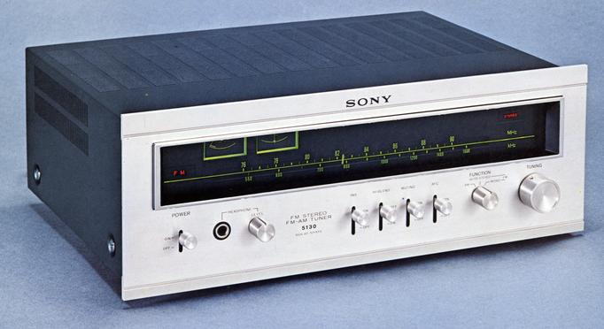
SONY ST-5130
¥ 69,800 (around 1972)
Commentary
In addition to pursuing the basic performance of the tuner, the high-grade tuner is equipped with functions such as INS equipment which cuts off the ignition noise of the automobile.
A precision 5-row varicon is adopted for the front end part, and a newly developed MOS FET is adopted for the high-frequency amplification and mixing stage to realize excellent interference rejection characteristics.
In addition, a new oscillator is used for the local oscillator, and the drift characteristic after the switch is turned on is excellent. Therefore, there is no problem such as detuning.
A newly developed 8-element solid-state filter is used in the IF stage to achieve sharp separation from adjacent channels.
This solid-state filter is fully unadjustable, does not change over time, and does not cause long-term detuning, so it can be used with stable sound quality for a long period of time.
Sony has developed and adopted a unique Impulse Noise Suppressor (INS) system that effectively cuts off vehicle ignition noise. This system cuts noise from vehicles passing nearby while receiving weak radio waves.
A five stage limiter, including a three stage symmetrical diode limiter, provides an excellent capture ratio and AM suppression effect.
FET is used for the MPX part in order to suppress distortion and obtain sufficient S/N.
An FET is also used in the muting circuit.
The AM part reduces beat interference, interference, distortion, etc.
It has an amplifier for headphones and a dedicated volume.
A multi-path observation terminal is mounted, and by connecting it to an oscilloscope, the state of the antenna and more accurate tuning can be confirmed.
75 Ω coaxial connector is mounted.
Equipped with two output terminals, fixed and variable.
Equipped with a center 0 tuning meter.
Equipped with a high-blend circuit, noise can be reduced with little loss of stereo effect when radio waves are weak and the S/N of the stereo broadcast transmission is insufficient.
.JPG)
Model Rating
| Type | FM/AM Tuner |
| Circuit system | Superheterodyne system |
| FM Tuner Section | |
| Antenna terminal | 300 Ω Balanced Type 75 Ω unbalanced type (coaxial cable connector) |
| Receiving frequency | 76 MHz to 90 MHz |
| Intermediate frequency | 10.7MHz |
| Practical sensitivity | 1.5 μ V (IHF) |
| Sensitivity | 1.2 μ V (S/N 30 db) |
| Signal-to-noise ratio | 75dB |
| Capture ratio | 1.0dB |
| Selectivity | 100dB(IHF) |
| Image interference ratio | 100dB |
| IF interference ratio | 100dB |
| Spurious interference ratio | 100dB |
| AM suppression ratio | 60dB(IHF) |
| Frequency characteristic | 20 Hz to 15 kHz, ± 1.0 dB |
| Distortion factor | Mono : 0.2% at 400 Hz, 100% modulation Stereo : 0.3% at 400 Hz, 100% modulation |
| FM stereo separation | 42 dB or More (400 Hz) |
| 19 khz and 38 khz suppression ratio | 60dB |
| Output Voltage / Impedance | Fixed output : 750mV/10k Ω (at 100% modulation) Variable output (Variable) : 0 ~ 2V/1.8k Ω (at 100% modulation at maximum output) |
| <AM Tuner Section> | |
| Antenna | Ferrite bar antenna With External Antenna Terminal |
| Receiving frequency | 530 kHz to 1,605 kHz |
| Intermediate frequency | 455kHz |
| Sensitivity | 50dB/m (when bar antenna is used) 30 μ V (when external antenna is used) |
| Signal-to-noise ratio | 50dB |
| Image interference ratio | 45dB(1MHz) |
| IF interference ratio | 41dB(1MHz) |
| Distortion factor | 0.6% |
| <General> | |
| Semiconductor used | Transistor : 46 pcs (Receiving Circuit : 22 pcs, Attached Circuit : 24 pcs) FET : 9 (Receiving Circuit : 4, Attached Circuit : 5) Diode : 41 |
| Pwer | 100 VAC, 50Hz/60Hz |
| Power consumption | 25W |
| External dimensions | Width 400x Height 149x Depth 344 mm |
| Weight | 7.5kg |
| Attachment | One FM feeder antenna Connection code RK-74x1 One Policing Cross 1 x 75 Ω F type plug |