.jpg)
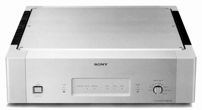
SONY DAS-R10
¥ 800,000 (around 1993)
Commentary
An R10 series D/A converter that uses a current pulse D/A converter.
The newly developed current-pulse D/A converter is used for the D/A converter.
The current pulse D/A converter is a single-bit D/A converter that uses current pulses. In the D/A converter, digital data is converted into a pulse train. In the conventional D/A converter, the pulse train is represented by a voltage. The voltage value that represents the pulse height is the power supply voltage applied to the converter IC. If the power supply voltage does not fluctuate, there is no problem. In reality, however, the power supply voltage fluctuates depending on the current consumption, and the height of the pulse train fluctuates slightly. In addition, since it is a voltage pulse, it is difficult to completely prevent the mixing of voltage noise generated by the arithmetic circuit, etc.. To avoid these problems, it is necessary to review the fact that the pulse is represented by a voltage.
The current pulse D/A converter used in the DAS-R10 converts the physical quantity used for D/A conversion from voltage to current, and is not affected by the noise of the arithmetic circuit, thus improving sound quality.
A current pulse is generated by alternately distributing a single DC current to two circuits. When a current flows through one circuit (when there is a pulse), the other circuit becomes 0, so that a pair of positive and negative current pulses are obtained. This allows perfect balance transmission over the entire audio signal path from the time of signal generation, reducing the influence of noise.
The current-pulse D/A converter has a feature of eliminating power supply voltage fluctuations and is rich in low-frequency expression. In addition, the newly developed complex voltage-current conversion circuit (CIV circuit), which converts current pulses into voltage waveforms, has noise elimination performance. Therefore, compared with voltage-type pulse D/A converters, there is less noise in the output signal, and a low-order low-pass filter with good group delay characteristics can be used as a low-pass filter in the latter stage. In addition, the CIV circuit itself has excellent performance in that there is no group delay degradation in the audio band good results such as high S/N ratio, sense of orientation, and sense of scale are obtained.
The digital filter uses a DSP parallel FIR type digital filter.
With conventional digital data, when the data is oversampled by 8 times, the original data is doubled to create intermediate data, and the next data is doubled. Each time intermediate data is created, new data is filled in between the original data and the data. With this serial method, there is a rounding error at the time of intermediate data creation, and this error accumulates every time operations are repeated.
The DAS-R10 uses eight DSPs, which have more computing power than a digital filter, and uses a parallel computing circuit that produces eight times more data than the original data at once, thus minimizing computation errors.
All the analog signal paths, including the current pulse D/A converter, are made of discrete component without the use of integrated circuits. Therefore, there are no restrictions associated with the use of ICs, and the performance is maximized.
In addition, there is no risk of noise contamination from the power supply system through the silicon substrate, which cannot be avoided with ICs.
A metal core module is used for the amplifier circuit.
This system consists of a metal core (metal substrate) made of aluminum alloy, heat-resistant insulating treatment, copper circuit patterns, and surface mounted components. The metal core itself is a metal with good thermal conductivity, so the heat balance of the circuit as a whole is extremely good. In addition, since it is divided into modules, it is more resistant to external vibration. In addition, surface mounted components do not have lead wires, so the contact between the lead wire and the component body can be omitted, and the vibration of the lead wire itself can be eliminated.
The motherboard for the digital circuit section and the D/A converter section uses a 4-layer board to connect signals at the shortest distance and to deploy power and ground on the entire surface.
As with the metal core module, surface mounting is positively adopted for mounting the components on the motherboard, shortening the signal path and improving the mounting density of the components.
The operation program of the DSP can be switched by the filter switch on the front panel. In the DAS-R10, the operation program is supplied from a ROM (read-only memory) installed outside the operation block. In addition to the normal ROM which is the standard mode, the ROM with the optional program written is installed, and it can be switched according to compatibility with the system and source.
.jpg)
.jpg)
.jpg)
.jpg)
.jpg)
Model Rating
| Type | D/A converter |
| Number of channels | 2 channels (stereo) |
| Frequency characteristic | 2 Hz ~ 20 kHz ± 0.5 dB (44.1 kHz, Filter Normal) |
| Signal-to-noise ratio | 110 dB or more (EIAJ) |
| Channel separation | 100 dB or more (EIAJ) |
| Total harmonic distortion factor | 0.003% or less (EIAJ) |
| Dynamic range | 100 dB or more (EIAJ) |
| Analog output | Unbalanced (pin-jack) : 2.5V/50k Ω / load impedance 1k Ω or more Balanced (XLR-3-32 equivalent) : 5 V / load impedance 600 Ω or more |
| Digital input | Electrical system Coaxial (pin jack) : 0.5Vp-p ± 10% / 75 Ω Balanced (equivalent to XLR-3) : 0.5 ~ 5.0Vp-p/110 Ω BNC (BNC Connector) : 0.5 ~ 5.0Vp-p/75 Ω Optical system OPT1 / 2 / 3 (Toslink) : -18dBm (emission wavelength 660 nm) OPT4 (STlink) : -18dBm (emission wavelength 850 nm) TwinLink : -18dBm (emission wave-length 800 nm) |
| Digital output terminal | BNC Coaxial Synchronous Output |
| Synchronous signal output | 44.1kHz |
| Pwer | 100 VAC, 50Hz/60Hz |
| Power consumption | 53W |
| External dimensions | Width 475x Height 140x Depth 425 mm |
| Weight | Approximately 25 kg |