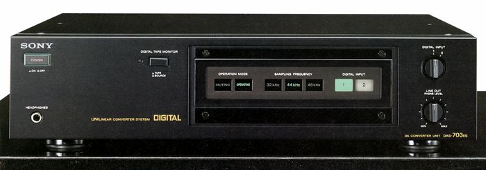
SONY DAS-703ES
¥ 250,000 (around 1986)
Commentary
D/A converter, the successor to DAS 702 es.
The layout of the DAS 703 es is divided into three parts, digital part, analog part and power supply part, and the construction is simple and follows the signal flow.
In addition, the digital part is contained in a shield case, and an optical transfer method using light is adopted for data transmission from the digital part to the analog part, which prevents the digital circuit from interfering with the analog circuit and degrading the sound quality.
We have reduced the size of the digital circuit in order to maximize the advantages of the digital separate system.
The digital circuit consists mainly of a data demodulation circuit and an oversampling digital filter. The data demodulation is processed by a single LSI (CX 23053) developed for the decoder.
The digital filter uses an LSI (CX 23034), which has an excellent filter attenuation of more than 80 dB.
A high-precision double PLL clock generation circuit is used for clock generation.
The clock required for the digital filter and data demodulation circuit must accurately track the jitter in the input signal, but the clock for the sample-and-hold circuit is the time axis of the analog output signal and must be prevented from tracking the jitter.
Taking these points into consideration, the DAS 703 es is designed as a high-precision double PLL that combines two PLLs with different characteristics : a digital PLL of jitter tracking type and an analog PLL of jitter non-tracking type.
An optical transfer method using an optical transmission element (photocoupler) is adopted for data transmission from digital circuit to analog circuit, which reduces various distortion and noise caused by ground current.
We have adopted a ladder type D/A converter IC.
In the ladder type, when 16-bit parallel data is input, a current corresponding to each bit is generated first, and then the sum is obtained through a resistor network called a ladder.
The DAS 703 es uses a current-output type, which is larger and more robust than the voltage-output type, which uses the internal resistance of the IC. It is also designed to use the voltage conversion itself as a sample-and-hold circuit. This effectively eliminates the need for an amplifier and provides fresher sound quality.
Equipped with a direct sample-and-hold circuit.
The sample-and-hold circuit samples only the latter half of the D/A converter IC, where the data is stable, and holds this value until the next stable data comes. This is because the output of the sample-and-hold circuit is distorted if the unstable value immediately after conversion of the input data of the D/A converter IC is output as it is.
The direct sample-and-hold circuit also directly converts current to voltage.
The analog low-pass filter uses a GIC type 7th order Butterworth active filter.
The output of the analog filter is output through an output amplifier that also serves as a de-emphasis circuit.
The DAS 703 es output amplifier combines a cascode dual FET with no capacity distortion at the first stage and a power MOS FET buffer circuit with a large current capacity at the output stage. This amplifier has sufficient volume and high-quality mid - and high-range.
The chassis is made to be a tough one by rationally combining structural materials of sufficient thickness and strength.
The insulator uses a vibration suppression structure that combines ceramics and non-resilient rubber.
The power supply section uses dedicated large transformers for both digital and analog circuits.
The analog one has a core volume that can make a power amplifier of about 100W. Also, the digital one is a little bit small but has a capacity that can cover the whole normal CD player.
Ceramic powder dispersion type electrolytic capacitor is adopted for electrolytic capacitor.
This condenser improves sound quality by dispersing fine ceramic powder in the electrolytic solution to activate the movement of abnormal noise in the electrolytic solution.
An ES board is used for the printed circuit board.
The resist coating on general printed circuit boards increases the capacitance between patterns, which has an effect on sound quality. On ES boards, the resist between patterns is removed to ensure sound quality with less hardness and distortion.
Resin molded acoustic resistor is used for the resistor.
Carbon film with a gold-plated cap The resistance element is molded with hard resin to improve sound quality and vibration. The DAS 703 es uses large, high-quality resistors for the NFB circuit and GIC filter to improve sound quality.
Digital Tape and Digital Rec out terminals are provided as dedicated input terminals for DAT and other devices.
If you press the Digital Tape Monitor switch on the panel, the input from Digital Input1/2 will be cut off and the input from this jack will be handled. The Digital Input1/2 signal will continue to be output to the Digital Rec out.
The DAS 703 es is designed to lock the PLL to any sampling frequency input between 32 and 48 kHz.
Equipped with 2 digital inputs.
LC-OFC wire is used for signal wire.
The line-out terminal is equipped with two systems, fixed and variable.
All input / output terminals are gold-plated.
.jpg)
.jpg)
.jpg)
.jpg)
.jpg)
.jpg)
.jpg)
Model Rating
| Type | D/A converter |
| Digital input | Digital Input1, 2, Tape : 0.5Vp-p ± 20% / 75 Ω |
| Digital output | 0.5Vp-p ± 20% / 75 Ω * Digital recording output is only output when the power is ON. * If the copy prohibited bit is added to the input digital signal, it will be output as it is. |
| Number of channels | 2 Channel |
| Decoding | 16-bit straight line |
| Frequency characteristic | 5 Hz ~ 20 kHz ± 0.5 dB (44.1 kHz or More) |
| Harmonic distortion factor | 0.004% or Less (1 kHz, 44.1 kHz, 16-bit) |
| Dynamic range | 95 dB or More (44.1 kHz at 16-bit) |
| Output Level / Impedance | Line out (fixed) : 2.5 V (digital signal max) / 10k Ω or more Line out (variable) : 0 V ~ 2.5 V (digital signal max) / 10k Ω or more Headphones : 0 mW ~ 14 mW (load 32 Ω, digital signal max) / 8 Ω or more |
| Pwer | 100 VAC, 50Hz/60Hz |
| Power consumption | 26W |
| External dimensions | Width 430x Height 110x Depth 435 mm |
| Weight | 16kg |