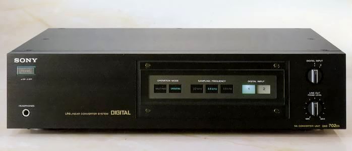
SONY DAS-702ES
¥ 200,000 (sold on November 21, 1984)
Commentary
SONY's No. 1 stand-alone D/A converter.
Adhering to the philosophy of the ESPRIT series, we pursue the highest priority for sound quality in all aspects of the circuit configuration, structure, and device.
The DAS 702 es is divided into three sections : a digital section, an analog section (including a D/A converter circuit) and a power supply section.
In addition to the audio circuit, the D/A converter section that uses a dedicated IC is used independently for Lch/Rch. This fully twin-mono configuration is used to thoroughly pursue sound quality. The digital section contains a clock generator, a data demodulation circuit, and an oversampling digital filter in a shield case to prevent the digital circuit from interfering with the analog and power sections.
The PLL circuit for clock generation is divided into Route 3 and composed of optimum circuits and constants for each region.
The PLL for the aperture, which is the time reference of the analog signal, is made independent to realize a circuit with high stability.
The data demodulation circuit uses a newly developed C-MOS LSI (CX23053) to decode the digital audio interface format input signal into normal 16-bit data, emphasis control signals, and other synchronization signals.
An over-sampling digital filter is installed. By increasing the sampling frequency, the band of the noise portion of the digitized signal component shifts to a higher frequency. This eliminates the need for a steep attenuation characteristic of the low-pass filter, which cuts the noise when returning the audio signal. This enables the use of a low-order low-pass filter with less distortion and phase shift.
The DAS-0ES uses the CX23034 digital filter that was developed for oversampling and has excellent characteristics such as a passband ripple of less than + 0.01 dB and a stop-global attenuation of more than 80 dB. 702 eS has excellent characteristics.
The D/A converter circuit uses a ladder-type IC, which provides current output when 16-bit parallel data is input. This circuit does not require a clock as seen in the integration type, making it very simple.
Compared with the integration type, the ladder type tends to have a slightly larger differential non-linearity error and has some disadvantages in terms of the distortion factor in the specification. However, we have obtained good results by adopting it and making the circuit simple.
The DAS 702 es uses two of these ICs to simultaneously add input data to the left and right channels to adjust the phase of the L and R channels.
To prevent distortion, a sample-and-hold circuit is installed to convert current values into voltage values. This circuit converts the current values into voltage values.
The output of the D/A converter circuit shows a new value at an interval of approximately 11 μ sec (at 44.1 kHz). This value is sampled for approximately 5.5 μ sec in consideration of a sufficiently stable timing and held for the remaining approximately 5.5 μ sec.
Since this sampling start point is the time reference of the converted analog value, the clock with high time axis accuracy generated by the aperture PLL of the clock generator is used.
A low-pal filter is installed to remove high-frequency components outside the audio band contained in the output signal of the sample-and-hold circuit.
In terms of circuitry, a GIC-type seventh order Butterworth active filter has been adopted, and audio signal components only pass through the resistance, which has succeeded in minimizing sound quality degradation.
The output amplifier is an audio op-amp.
Especially fTThe frequency at which the current amplification factor hfe becomes 1 is extended to approximately 700 MHz. The PNP side, which is usually around 1 to 2 MHz, is an excellent process that achieves almost the same performance as the NPN side. The element structure with good thermal balance and IC package with large heat capacity make use of Sony's tradition.
In addition, we use a lot of carefully examined materials such as simple and straight transmission by twin mono circuit configuration of L/Rch separation using bus bar, LC-OFC wire material, metal coating resistance, etc.
The power supply section includes a large-capacity (190 VA) power transformer with two windings for analog and digital circuits, an ultra-high-speed rectifier diode, and a large ceramic powder electrolytic capacitor with a total capacitance of approximately 33,000 μ F. The power supply section has sufficient space. The wiring material used is LC-OFC, a type I oxygen-free copper with a purity of 99.995% or more and with significantly fewer crystal boundaries.
The chassis is designed to be highly rigid. As a measure against vibration, the main printed circuit board (analog part / power supply part) and the shield case of the digital circuit are fixed with a 4mm-thick aluminum bottom plate and a 10mmx15mm-square aluminum material.
In addition, the top plate is a 3mm-thick aluminum plate, and damping materials are also used. The entire chassis is vibration-proof structure using a lot of non-magnetic materials to prevent magnetic distortion.
Since the digital audio interface transmits two L and R channel data in a single line, it uses a time division multiplex transmission method in which L channel data and R channel data are alternately transmitted and received.
When the sampling frequency is 44.1 kHz, 88,200 data are transmitted on both channels at a rate of 44,100 data per second. The length of each channel data section is 11.34 μ sec. Each word consists of 32 bits. The first 4 bits are the SYNC part for synchronization, the next is the 24-bit field for audio data, and the last 4 bits are the part for emphasis ON/OFF and information accompanying data such as subcodes.
The data thus assembled is subjected to a modulation called biphase mark, in which data 0 is inverted once and data 1 is inverted twice. However, in the SYNC part, a special pattern called preamble is embedded, and the inversion by data is ignored, so that the duration of high level is longer than other parts.
The D/A converter uses this preamble part for synchronization.
Equipped with an indicator capable of automatic switching for sampling frequency of 32kHz/44.1kHz/48kHz.
Equipped with two digital input / output terminals.
The line-out terminal is gold-plated with two systems, FIX (fixed) and VARIABLE (variable).
It uses a variable volume with carefully examined sound quality, and the level of line output and headphone output can be adjusted.
.JPG)
.JPG)
.JPG)
.JPG)
.JPG)
.JPG)
Model Rating
| Type | D/A converter |
| Digital input | 0.5Vp-p ± 20% / 75 Ω |
| Digital output | 0.5Vp-p ± 20% / 75 Ω |
| Number of channels | 2 Channel |
| Decoding | 16-bit straight line |
| Frequency characteristic | 5 Hz ~ 20 kHz ± 0.5 dB (44.1 kHz or More) |
| Harmonic distortion factor | 0.004% or Less (1 kHz, 44.1 kHz, 16-bit) |
| Dynamic range | 95 dB or More (44.1 kHz at 16-bit) |
| Output Level / Impedance | Line Out (fixed) : 2 V (digital signal, MAX) / 10k Ω or more Line Out (Variable) : 0 V ~ 5 V (Digital Signal, MAX) / 10k Ω or more Headphones : 0 mw ~ 140 mw (32 ohm load, digital signal, MAX) / Low |
| Pwer | AC100V |
| Power consumption | 23W |
| External dimensions | Width 430x Height 105x Depth 410 mm |
| Weight | 11.5kg |