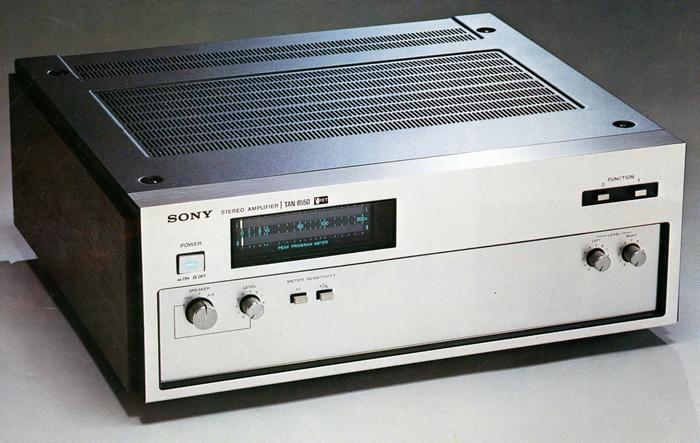
SONY TAN-8550
¥ 295,000 (around 1974)
Commentary
A high-grade stereo power amplifier employing a newly developed V-FET in order to realize the theme of waveform transmission in which the waveforms of input and output signals are similar as they are.
The V-FET is a power FET with a vertical structure, while the conventional FET has a horizontal structure. The V-FET realizes a vertical structure by a unique manufacturing method and selective oxidation method.
This V-FET has static characteristics similar to those of a triode vacuum tube. However, it can handle current more than one order of magnitude larger than that of a triode vacuum tube. Moreover, the V-FET has a lower output-resistance. Moreover, since both N-channel and P-channel bipolar elements can be obtained, there is no need for a phase-reversal circuit like a tube, and a pure complimentary service output-stage can be obtained.
In addition, the V-FET shows linear transmission characteristics, and the output current is proportional to the large amplitude input voltage applied to the V-FET, and the output waveform can be amplified with good linearity with very little high-order harmonic distortion.
Since the V-FET does not have a carrier storage effect like a transistor, its switching speed is remarkably fast and its storage time is hardly recognized, so its switching distortion is greatly reduced.
In addition, the V-FET has a wider ASO (safe operating region) than bipolar transistors. Moreover, the channel regions are distributed in parallel, making it difficult for current concentration to occur. In addition, the negative temperature coefficient has a self-controlling effect against heat generation. As a result, the V-FET is resistant to thermal breakdown (secondary breakdown). In addition, temperature compensation is not necessary because the operating point varies very little with temperature.
The B-class stage employs a triple push-pull pure complimentary service circuit using newly developed N-channel and P-channel V-FETs. This circuit uses six V-FETs per channel to achieve high output. In addition, the V-FET characteristics improve the distortion factor characteristics in the high frequency range and provide a good operating range even under low impedance loads.
The high input impedance and low output impedance characteristics of the V-FET transmit superior A-class characteristics to the speaker.
Class A is a 3-stage differential amplifier configuration.
The first stage employs a newly developed dual FET in which two high input impedance FETs with uniform characteristics are packaged in one package. There is no temperature drift, so unbalanced voltage does not occur. The second and third stages are differential amplifier configuration using PNP and NPN with good bare characteristics.
All the A-Class stages have built-in constant-voltage circuits that are always stable against fluctuations in the power supply voltage to prevent noise from the power supply.
Newly developed electrolytic capacitors for two power supplies are used in the power supply section.
This capacitor contains two capacitor elements in one pack. The resistance value is one order of magnitude smaller than that of conventional capacitors, and the mutual inductance and self-inductance are also reduced.
In addition, ground impedance is reduced by connecting two elements wound on a concentric circle to the grounding terminal at the shortest distance. Since each element has a non-inductive structure, high-frequency impedance and leakage flux are greatly improved. The connection is also simplified by using the one touch weld method.
A newly developed chimney type heat sink is used for the heat sink.
The chimney type uses air convection to allow heated air to rise through the duct and cold air to be sucked from the lower part of the heat sink, enabling stable operation of the V-FET even at high output power.
The power meter uses an optical peak program meter.
This power meter uses a light beam system (light indication system), and it has good tracking ability for a pulsed signal and can give peak indication. Moreover, the dynamic range of the meter is extremely wide.
The meter scale is W and can display RMS values from 0 to 200 for 8 Ω load. In order to make it easier to see the meter even when listening at an output of 20W or less, the meter is equipped with an x1/10 meter sensitivity switch on the front so that you can see the meter at 10 times the actual output.
It is equipped with a Route 3 speaker connector.
Jack A is a normal output jack and jack B is level adjustable. The direct jack is useful when you are concerned about the deterioration of the damping factor caused by the speaker switch. You can adjust the level of this direct jack by adjusting it to position B.
It is equipped with a subsonic filter to prevent ultra low-frequency noise caused by warping of records, etc.
This circuit can be turned ON/OFF with the normal / test change-over switch. In the test position, it is output as it is, and in the normal position, it cuts out the outside of the audio band.
A full protection circuit is used for the protection circuit.
A purely electronic DC detection circuit is used to protect the speakers from damage by limiting the DC voltage, and a load impedance detection type protection circuit with a PC limiter is used to protect the V = FET from short-circuit.
In addition, to prevent transistor damage due to abnormal heat generation, a heat detection type protection circuit is adopted.
Equipped with input level control.
.JPG)
.JPG)
.JPG)
.JPG)
.JPG)
Model Rating
| Type | Stereo power amplifier | ||||
| Circuit system | Phase-linear DC amplifier configuration V-FET Triple Push-Pull Pure complimentary service Symmetry Circuit |
||||
| Amplifier Unit | |||||
| Effective output (both channel operation, harmonic distortion 0.1%) |
|
||||
| Output bandwidth | 5 Hz ~ 50 kHz (IHF Standard, 8 Ω) | ||||
| Harmonic distortion factor | 0.1% or Less (at Rated Output) 0.05% or Less (at 1W Output) |
||||
| Intermodulation distortion factor (60 hz : 7 khz = 4 : 1) | 0.1% or Less (at Rated Output) 0.05% or Less (at 1W Output) |
||||
| Frequency characteristics (8 Ω load, 1W output) | Test : DC ~ 100 kHz + 0 -1dB Normal : 20 Hz to 100 kHz + 0 -3dB |
||||
| Damping factor (1 kHz) | 200 or More (8 Ω, Speaker Direct Terminal) | ||||
| Input Sensitivity / Impedance | 1 V (Rated Output) / 50k Ω Route 2 |
||||
| Output terminal | Speaker A, B, Direct | ||||
| Residual noise | 0.01 μ W or less | ||||
| Signal-to-noise ratio | 100 dB or more closed circuit) | ||||
| Optical Peak Program Meter Section | |||||
| Frequency characteristic | 30 Hz ~ 30 kHz + 0 -3dB | ||||
| Meter indication range | 0W ~ 200W | ||||
| <General> | |||||
| Semiconductor used | Transistor : 56 pcs Dual FET : 2 units V-FET : 12 Diode : 54 pcs SCR : 2 |
||||
| Power outlet | Power switch not linked : 1 system, 200W | ||||
| Pwer | 100 VAC, 50Hz/60Hz | ||||
| Power consumption | 260W | ||||
| External dimensions | Width 440x Height 170x Depth 410 mm | ||||
| Weight | Approximately 19 kg | ||||