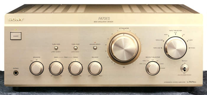
SONY TA-FA70ES
¥ 180,000 (released in 1997)
Commentary
A pre-main amplifier developed as a reference for the Sony ES amplifier.
All stages of the circuit are composed of MOS-FETs.
MOS-FETs have excellent high-frequency characteristics and excellent switching speed as amplification elements. They also have the advantage that the front and rear stages are less likely to interfere with each other due to high input impedance. In addition, there is less strain in the headmaster of odd orders such as 3rd and 5th, which are easy to hear in terms of distortion characteristics, and the crossover distortion caused by connecting push-pull circuits can be greatly reduced compared to the conventional bipolar and r-type G-ster.
A non-magnetic type is adopted for the power MOS-FET of the final stage, which is gold-plated.
In order to take advantage of the all-stage MOS-FET configuration, the bias circuit is equipped with an optical element with the same temperature characteristics as the MOS-FET to suppress the fluctuation of idling current and make operation more stable. In addition, the coupling capacitor in the bias circuit is also increased in capacity to reduce impedance, thereby completely suppressing the generation of unnecessary harmonics and realizing sound with less distortion.
It uses a fixed optical bias circuit.
The TA-FA70ES takes advantage of the MOS-FET's ability to operate stably even when the temperature of the element fluctuates. The TA-FA70ES eliminates the transistor temperature detection and compensation, and the thermal sensor is a virtually fixed bias circuit that only detects gradual temperature changes in the chassis. This stabilizes the bias current, eliminates the sense of instability immediately after the peak of the music signal, and realizes a relaxed sound quality that is difficult with bipolar transistors.
The power supply section is equipped with an improved torus and toroidal transformer.
The toroidal transformer reduces vibration by increasing the adhesion between the core and the coil by making the section of the iron core (core) elliptical. This reduces the overall length of the winding and reduces impedance, resulting in an increase in power capacity at the same size.
The TA-FAthe TA-FA70ES has been greatly increased in capacity to 600 VA. In addition, the primary winding (AC100V side), which was previously wound on the outside, has been changed to the inside, and the secondary winding is wound on the outside, so that the noise contained in the AC100V line is enclosed and is not radiated into the chassis. In addition, the bifilar wiring, in which the lengths of the + and - side windings are equal, has been adopted to improve the S / N ratio in the sense of hearing.
The power supply circuit uses an advanced S. T. D. power supply.
In the S. T. D. power supply, the rectifier circuit of the power supply section is provided separately for the voltage amplification stage (A-class stage) and the power amplification stage (power stage), thereby eliminating the influence of power amplification with large current variation on the voltage amplification stage.
The Advanced S. T. D. power supply has been further improved by increasing the size of the transformer and changing the specifications of the high-capacity electrolytic capacitor to obtain more stable power supply capability.
The internal layout uses twin monaural construction. The power supply unit is placed in the center of the chassis. The left and right power amplifiers and heat sinks are arranged almost symmetrically to sandwich the power supply unit. The heat sink is also arranged with the fin inside so that the power MOS-FET of the final stage is far from each other and away from the transformer.
This achieves good channel separation with little crosstalk.
The chassis is composed of five blocks. In order to reduce the influence of the power amplifier and power supply, which handle large current, on the preamplifier for small signal, the chassis is divided into one preamplifier, two power supply, power supply for 3 lch, power supply for 4 rch, and five control sections. This reduces electromagnetic interference and vibration interference.
Copper plating of the FB chassis and heat sink reduces eddy current.
An eccentric insulator is used for the legs.
FET is used for phono input circuit for MM/MC cartridge.
It uses carefully selected parts such as inert gas-filled relays, carbon resistors, OFC internal wiring materials, and high-quality electrolytic capacitors.
It is equipped with a balanced input by XLR-type terminal which is less affected by noise in the transmission path.
The input circuit uses a metal core module in which parts are surface-mounted on a metal substrate treated with heat-resistant insulation.
Using a pure input circuit, the number of contacts from the input terminal to the master volume is greatly reduced to protect the weak audio signal.
The tone control section has a turnover switching function.
It is equipped with a source direct switch and can bypass tone control and balance control circuits when these circuits are not required.
Built-in pre-out terminal.
.jpg)
.jpg)
.jpg)
.jpg)
.jpg)
.jpg)
.jpg)
.jpg)
.jpg)
Internal layout of the production version and internal layout of the prototype version
In the February 1997 catalog, the internal layout and rear panel of the prototype model were shown instead of the finished product. It seems that there was a change just before the release. If you take a closer look, there are changes in the details, as far as I checked.
・ Changing the shape of the upper part of the transformer.
・ Changing the shape of a gold-plated speaker terminal.
・ It is omitted that the final-stage power MOS-FET was fixed by sandwiching it between aluminum plates.
・ The shape of the front panel fixed part has been changed from a trapezoid to a square.
・ The black painted part of the rear panel is reduced.
・ Cushioning material for vibration reduction has been added to the side frame.
- Addition of black reinforcing plates at the four corners of the frame.
It seems to have been changed.
.jpg)
Fixing portion of power MOS-FET
In the February 1997 catalog, the explanation also showed how to fix the power MOS FET.
According to the explanation, the effect of vibration and non-linear hysteresis response were eliminated by fixing the heat sink to be sandwiched between thick aluminum plates.
Model Rating
| Type | Pre-main amplifier | ||
| Effective output (20 Hz to 20 kHz) | 120W + 120W (4 Ω) 100W + 100W (6 Ω) 80W + 80W (8 Ω) |
||
| Input Sensitivity / Impedance | Phono MM : 2.5mV/50k Ω Phono MC : 170 μ V/100 Ω Line : 150mV/50k Ω |
||
| Output Level / Impedance | Rec out : 150mV/1k Ω Headphone : 25 mW (8 Ω) |
||
| Total harmonic distortion factor | 0.008% (8 Ω at 10W output) | ||
| Intermodulation distortion factor (60 hz : 7 khz = 4 : 1) | 0.008% (8 Ω at rated output) | ||
| Frequency characteristic | Phono MM : 20 Hz to 20 kHz ± 0.2 dB Line : 2 Hz to 100 kHz + 0 -3dB |
||
| Signal-to-noise ratio | Phono MM:87dB Phono MC:76dB Line:105dB |
||
| Tone control |
|
||
| Accessory function | Source direct switch Rec out off Rec Out Selector Turnover switching function |
||
| Pwer | 100 VAC, 50Hz/60Hz | ||
| Power consumption | 230W | ||
| External dimensions | Width 430x Height 175x Depth 450 mm | ||
| Weight | Approx. 23 kg |
.jpg)