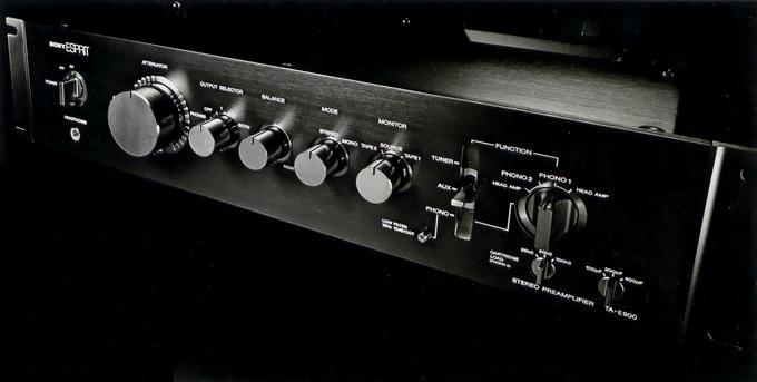
SONY/ESPRIT TA-E900
¥ 600,000 (released in 1981)
Commentary
This is a stereo control amplifier that has achieved a high level of perfection in both characteristics and sound quality by taking all possible approaches from all aspects of the circuit technology, material and mechanism that form the three elements of the amplifier.
The MC head amplifier section consists of a push-pull amplifier with a grounded base. The linearity is improved by cascode connection. Since the grounded base amplifier only amplifies the voltage by impedance conversion, the current supplied from the power supply is only a DC bias current, and there is no variation due to music signals. Therefore, it is hardly affected by the power supply and the influence on the power supply is very small.
The first stage of the equalizer amplifier section is a differential amplifier using a dual FET. This FET has the same electrical characteristics, good thermal balance, high mutual inductance and low feedback capacitance. It is specially designed to compensate for stable operation with a good S/N ratio. Each element has a cascode-bootstrap connection to further reduce the apparent feedback capacitance, improve the high-frequency characteristics and make it less susceptible to power fluctuations.
The second stage is a differential amplifier using a PNP transistor. As in the first stage, a cascode connection is used to equalize collector losses in both of the differential pair transistors to prevent temperature drift, improve linearity and reduce distortion.
The output stage is a Darlington emitter follower PP type so that it can cope with a certain amount of load.
The two amplifier circuits, the input buffer amplifier and the flat amplifier, differ only in gain due to the difference in feedback resistance, and differ from the equalizer amplifier only in the configuration of the feedback element and the first stage FET.
The input buffer amplifier is a DC amplifier with 100% negative feedback and gain of 0 dB. It receives an input with high impedance and drives an attenuator or balancer with low impedance. It is used to prevent degradation of characteristics at the time of Tuner and Aux inputs.
The flat amplifier is a DC-amplifier with a gain of 20 dB. The series resistance of the connection code is as small as 100 Ω to suppress the deterioration of the frequency-response characteristics due to the capacitance of the output and to cope with a wide range of load conditions.
A buffer amplifier with a gain of 0 dB is inserted in the TA-E900 in order to prevent the excessive load caused by sending the source signal to Rec out with multiple tape recorders connected, or the deterioration of sound quality caused by the input transistor of the recorder acting as a non-linear element when the power is turned off with the tape recorder connected.
The secondary output of the power transformer is rectified by a high-speed diode and then stabilized by a constant voltage circuit.
The constant voltage circuit consists of a two stage differential error amplifier circuit and an emitter follower. High ripple rejection and low output impedance characteristics are obtained by the combination of a highly stable low current power supply.
The resistors of attenuators and balancers are made of a metal film deposited on an alumina substrate. The conductor that contacts the slider is gold-plated. The resistance value is reduced to 3k Ω to suppress thermal noise and prevent degradation of high-frequency characteristics due to the influence of distributed capacitance.
In addition, the body is composed of zinc die-cast and aluminum, and serves as a shield.
We use audio amplifiers that satisfy linearity, frequency characteristics, input capacitance, feedback capacitance, and other characteristics. We also select resistors with good temperature characteristics, allowable deviation, and distortion factor (10 kHz third harmonic) for sound quality. In particular, we use resistors for signal paths that have a sufficient margin for allowable power. Depending on the location, series or parallel connection is used.
In order to prevent mechanical resonance and loss caused by applied voltage, film is tightly wound and the periphery is fixed. In addition, the electrode and film itself are selected to have excellent mechanical strength and electrical characteristics.
High-purity aluminum foil is used for both the anode and cathode foils of the electrolytic capacitor for rectification of the power supply section. We have adopted a chemical conversion method that is most suitable for the subsidiary coating in terms of sound quality, a high-speed low-distortion type electrolytic solution, materials from the terminal to plating are examined, and magnetic substances are eliminated. We have made improvements through repeated studies.
Class 1 oxygen-free copper (copper-purity 99.99% or more) is used as a conductive material for printed circuit boards and wiring materials.
In the construction of the TA-E900, the left and right channels are completely separated including the power supply.
In addition, the elements and parts are arranged along the signal flow and directly attached to the printed circuit board to avoid wire wiring, and signal interference not only between left and right channels but also within the same channel is suppressed.
Both the attenuator and the balancer are contained in a single case for both the left and right sides. A shield plate is provided between them to improve the separation of the left and right sides without losing the linkage, and the switch for changing the signal system is operated by the link.
The input / output terminals are concentrated in one place, and by concentrating these grounds, the difference in ground potential (earth potential) is extremely small, eliminating mutual interference.
In consideration of the adverse effect of mechanical vibration on electric circuits, we have adopted a vibration isolation structure.
First, we use a robust chassis structure based on a thick aluminum frame to minimize vibration of printed circuit boards and parts. We also use a modular system in which amplifier circuits are unitized and the whole is hardened with resin. This resin has excellent thermal conductivity and prevents thermal distortion of parts caused by fluctuations in power consumption.
.JPG)
.JPG)
.JPG)
.JPG)
.JPG)
.JPG)
.JPG)
.JPG)
Model Rating
| Type | Stereo preamplifier | ||||||
| Circuit system |
|
||||||
| Input sensitivity / Impedance |
Phono1 : 2.5mV/50k Ω / 100 pH Phono1 (Head amp 40 Ω) : 0.2mV/4 Ω Phono1 (Head amp 4 Ω) : 0.035mV/4 Ω Phono2 : 2.5mV/25k Ω, 50k Ω, 100k Ω / 100 pF, 200 pF, 400 pF Phono2 (Head amp 40 Ω) : 0.2mV/4 Ω Phono2 (Head amp 4 Ω) : 0.035mV/4 Ω Tuner, Aux, Tape1, 2 : 150mV/50k Ω |
||||||
| Maximum Allowable Input (1 kHz) | Phono1:180mV Phono1 (Head amp 40 Ω) : 15 mV Phono1 (Head amp 4 Ω) : 2.5 mV Phono2:180mV Phono2 (Head amp 40 Ω) : 15 mv Phono2 (Head amp 4 Ω) : 2.5 mV Tuner, Aux, Tape1, 2 : 12 v |
||||||
| S/N IHF-A Network |
Phono1:84dB Phono1 (Head amp 40 Ω) : 72 dB (input conversion noise -158dB/V) Phono1 (Head amp 4 Ω) : 65 dB (input conversion noise -158dB/V) Phono2:84dB Phono2 (Head amp 40 Ω) : 72 dB (input conversion noise -158dB/V) Phono2 (Head amp 4 Ω) : 65 dB (input conversion noise -158dB/V) Tuner, Aux, Tape1, 2 : 102 dB |
||||||
| Output level / Impedance |
Rec out1, 2 : 150 mv (maximum 12 v) / 100 Ω Output1, 2 : 1.5 V (maximum 12 V) / 100 Ω |
||||||
| Harmonic distortion factor | 0.005% or Less (at 8 v Output) | ||||||
| Cross modulation distortion factor | 0.005% or Less (at 8 v output, 60 hz : 7 khz = 4 : 1) | ||||||
| Frequency characteristic | Phono1 and 2 : RIAA curve ± 0.2 dB Tuner, Aux, Tape1, 2 : DC ~ 300 khz + 0 -1dB |
||||||
| Filter (Phono input) | Low : 12dB/oct (cutoff frequency 15 Hz) | ||||||
| Residual noise | 12 μ V (IHF-A network) | ||||||
| Auxiliary power outlet | Switched : 1, up to 450W Unswitched : 1 line, up to 450W |
||||||
| Pwer | 100 VAC, 50Hz/60Hz | ||||||
| Power consumption | 18W | ||||||
| External dimensions | Width 480x Height 105x Depth 455 mm | ||||||
| Weight | 13kg | ||||||
| Rack mount | Possible with JIS standard rack (mounting pitch 50 mm) | ||||||
| Accessories | 2 short plugs Dust Cap x18 |