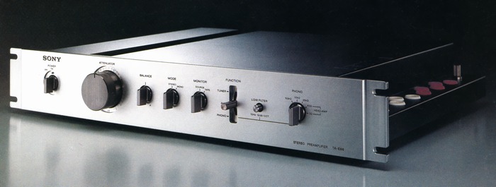
SONY TA-E86
¥ 90,000 (released in 1978)
Commentary
A DC preamplifier developed by inheriting the concept of amplifier making in the TA-E88.
In general amplifiers, the volume and switches are arranged on the front panel, and the input / output terminals are arranged on the rear panel. Although this layout is reasonable in terms of usability, signal degradation due to lead wiring was unavoidable. The TA-E86 eliminates this restriction and uses a component layout that gives priority to signal flow.
The internal layout of the TA-E86 is such that the left and right channels are clearly separated by a shield plate. The volume and balance volume are directly attached to the printed circuit board near the shield plate for both L and R signal systems. The switches are also installed in separate positions for L and R, and they are interlocked and switched by the shaft from the front. In addition, all signal components are directly attached to the printed circuit board to prevent electromagnetic induction caused by lead wire routing.
Functions such as tape copy switches and tone such as tape copy switches and tone controls, are eliminated as much as possible, and a simple circuit structure is used to improve sound quality.
Equipped with an equalizer amplifier of DC configuration.
The first stage is a cascode connection of differential amplification by dual FET, which suppresses degradation of high frequency characteristics and prevents mixing of unnecessary components due to external noise such as hum and power supply fluctuation by combination with constant current circuit. The second stage is a cascode connection of differential circuit by dual transistor, which reduces temperature drift and improves output linearity and distortion factor.
Since it is a DC amplifier without an input capacitor, there is no low-frequency phase rotation.
The flat amplifier section has the same circuit configuration as the equalizer amplifier except for the circuit constant and time constant circuit.
The DC amplifier configuration prevents degradation of low-frequency characteristics.
The MC head amplifier employs a newly developed ultra-low-noise transistor, LEC-II, which is equivalent to the conventional parallel connection of 10 low-noise transistors, and realizes a high SN ratio.
The circuit configuration is a single-stage differential and two cut-off direct-coupled configuration with Darlington connection. This circuit is almost equivalent to the HA-55 single head amplifier.
It is equipped with a base boost amplifier as an auxiliary for miniature speakers.
In general tone control, the entire low-frequency range is raised, but in the base boost amplifier, the volume of the low-frequency range is not lost because the boost is centered around 100 Hz, while in the ultra-low-frequency range below 80 Hz, the volume of the low-frequency range is not lost. In addition, the volume of the ultra-low-frequency range below 80 Hz is reduced so that the speaker is not overwhelmed.
The Phono circuit is equipped with a low filter, which can cut out very low frequency harmful components such as sleds of records.
It is also equipped with a 5-stage cartridge load selector.
Separate FET buffer power supplies are provided for the head amplifier and the equalizer / flat amplifier.
This improves the crosstalk characteristics by suppressing fluctuations in the input voltage with high capability and by reducing the low-output impedance characteristics.
The newly developed volume has excellent characteristics such as crosstalk, square-wave response, and distortion factor.
Uses high-quality parts that have been carefully examined, selected, and developed in consideration of sound quality changes depending on the parts.
A polypropylene film capacitor is used for the NF element. In this capacitor, the electrodes are finely divided by using a thick insulator with high rigidity for the insulation between the electrodes to reduce the electric field strength and suppress mechanical resonance.
In addition, high-precision metal film resistors with temperature characteristics of ± 50 mm and allowable deviation of less than 1% are actively used at important points to suppress deviation and drift of frequency characteristics.
A copper plate of 1 mm thickness with a U-shaped cross section is used for the common ground of the left and right channels to reduce impedance by reducing resistance value.
Gold-plated terminals are used for input / output terminals.
Equipped with quick access type function selector, tape monitor switch and mode switch.
.JPG)
.jpg)
.jpg)
.jpg)
.jpg)
.jpg)
Model Rating
| Type | Control amplifier |
| Circuit system | Low noise head amplifier NF type equalizer amplifier with DC configuration DC configuration flat amplifier Two system constant voltage power supply |
| Input Sensitivity / Impedance | Phono : 2.5mV/25k Ω, 50k Ω, 100k Ω Headamp : 0.125mV/100 Ω (40 Ω position), 25 Ω (3 Ω position) Tuner, Aux, Tape : 150mV/50k Ω |
| Output Level / Impedance | Rec out : 150 mv (maximum 13 v) / 10k Ω Output : 1.5 V (maximum 13 V) / 100 Ω |
| Signal-to-noise ratio (IHF-A) | Phono:87dB Headamp:78dB(0.2mV) Aux:100dB |
| Maximum Allowable Input (1 kHz) | Phono:250mV Headamp:12.5mV |
| Harmonic distortion factor | 0.003% (at 10 v output) |
| Cross modulation distortion factor | 0.003% (at 10 v output, 60 hz : 7 khz = 4 : 1) |
| RIAA deviation | + / - 0.2 dB |
| Frequency characteristic | Tuner, Aux, Tape : 5 hz to 500 khz + 0 to 1 db |
| Low filter | 15 Hz, 12dB/oct. (Phono Input) |
| Base boost | + 6 dB (120 Hz, Output2 only) |
| Residual noise | 6 μ V or less (A Network, IHF) |
| Semiconductor used | Transistor : 90 FET : 22 Diode : 20 pcs |
| Power outlet | Switched : two systems Unswitched-One system Up to 900W total |
| Pwer | 100 V, 50Hz/60Hz |
| Power consumption | 15W |
| External dimensions | Width 480x Height 80x Depth 366 mm |
| Weight | 8.2kg |
| Attachment | Low-volume connection code Dustproof Cap x14 |
.jpg)