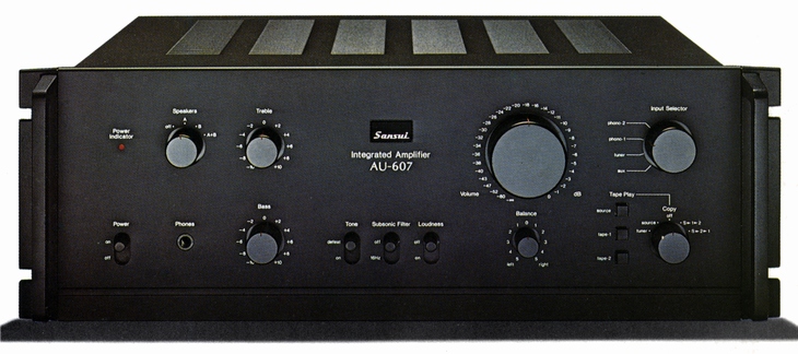
SANSUI AU-607
¥ 69,800 (released in 1976)
Commentary
This pre-main amplifier was developed in pursuit of physical characteristics under the development theme of creating new sound with a novel circuit that understands the essence of audio.
When a program source with a large dynamic range and a dense music signal is reproduced by an amplifier with a large bare gain and a large amount of NF applied to improve the distortion, transient intermodulation distortion (Transient Intermodulation) occurs due to an unstable element such as delay in the amplifier circuit, and the resolution deteriorates. Transient Intermodulation Distortion (TIM) occurs at the summing point, which is the synthesis point of the input signal and NF signal, because the NF operation is momentarily lost due to the delay in the circuit, and an excessive input enters the amplifier. Therefore, it was difficult to achieve a wide range with conventional amplifiers.
In the AU 607, we examined the bare characteristics before applying NF, and expanded the frequency characteristics, improved the phase characteristics, and reduced the distortion factor. We also improved the phase characteristics up to several tens of MHz by combining a unique phase correction circuit with an appropriate stagger ratio for phase advance and phase delay. By applying the minimum necessary NF, the transient intermodulation distortion is improved. As well as excellent response in the ultra-low frequency range, response in the ultra-high frequency range is improved, and wide-range playback is enabled.
The power amplifier section uses a DC amplifier configuration.
A newly developed dual FET with the same characteristics is used in the first stage. This device has a feature that allows a large current to flow approximately four times that of conventional FETs. Taking advantage of this feature, it improves the slew rate and prevents the generation of transient intermodulation distortion at the summing point where the input signal and NF signal are synthesized.
The second stage employs a differential two stage amplification configuration using a low-noise transistor.
In this circuit, gain is suppressed as much as possible to improve bare characteristics. In addition, a unique current mirror circuit and cascode connection are used. In addition, current differential operation is performed from the single-end output of the second stage. The pre-drive stage is configured. Because this circuit is a push-pull circuit, the second harmonic wave is canceled out, and the circuit configuration is excellent in bare characteristics and distortion rate characteristics. Moreover, it is not affected by temperature characteristics and power supply fluctuation. The transistor of this pre-drive stage is carefully selected with a particularly small hoe (emitter grounding, output conductance). In addition, a series resistor is added to the emitter side to eliminate linearity deterioration due to hoe.
The output stage is a 3-stage Darlington configuration. This reduces output impedance and reduces distortion. In addition, the output transistor has good high-frequency and pulse characteristics, and stable operation with margin is obtained.
As for the drift of mid-point potential, which is a problem in DC amplifiers, the DC amplifier configuration is made after realizing stability of drift by suppressing power supply fluctuation thoroughly so that the first stage of the amplifier is not affected by the output, and improving the symmetry (pair characteristic) of the summing point.
The equalizer amplifier section consists of 8 transistors consisting of 1 stage differential with first stage current source, 1 stage class A amplifier with buffer and activator, and final stage pure complimentary service SEPP output-circuit. The signal system consists of 6 transistors. As with the DC power amplifier section, the circuit design is simple and substantial. Bare characteristics are emphasized, and low distortion is realized in a wide range outside the audible band (10 hz to 100 khz).
In particular, a low-noise transistor is carefully selected for the differential input, and a current source circuit is added to improve the CMRR (in-phase component rejection ratio) at the summing point where the input signal and the NF signal are combined to improve the dynamic characteristics.
In addition, a pure complimentary service SEPP circuit is used in the EQ output stage to obtain a high signal-to-noise ratio and sufficient dynamic merging together with sufficient gain.
RIAA deviation is kept within ± 0.2 dB by using a high-precision metal film resistor and a capacitor with low capacitance error, and dynamic margin is obtained by using ± 2 power supply of high voltage with good regulation.
The tone control section consists of four transistors, first stage differential amplification with current source + first stage amplification. The tone control section uses a click-type variable element to adjust sound quality with a good feeling.
In addition, a tone defeat switch is installed for cases where tone adjustment is not required. The tone circuit is eliminated and flat frequency characteristics can be obtained by flat amplifier.
Equipped with a subsonic filter, it can cut unwanted noise in the ultra low frequency range.
Two power transformers are used in the power supply section to ensure that the left and right channels are completely independent, thereby preventing crosstalk to other channels and improving regulation.
The power supply capacitor is designed to have a large capacity of 12,000 μ Fx4 to provide a stable ± 2 power supply to each circuit. In addition, the use of metallized film capacitors and constant voltage power supply circuits reduces the internal impedance of the power supply, which affects the reproducibility of sound quality. As a result, we have achieved good articulation in the low frequency range and good sound thickness and resolution in the middle and high frequency range.
The protection circuit incorporates an ASO (Safe Operating Area) detection current limiter circuit and a DC detection circuit for the output terminal for high reliability.
The volume is a 32-step click type that uses a 2-row detent type with less left / right channel tracking error and indication error.
The preamplifier section and DC main amplifier section can be separated.
The main amplifier section can be used independently, and DC input or AC input can be selected as input.
It is equipped with tape play circuit, and 2 tape decks can be used.
Tape play function such as air check while listening to the record and tape copy can be performed independently.
Equipped with a loudness function.
In addition, it is equipped with center click type balance control, headphone port, large earth port, spare AC outlet and so on.
There was a rack mount adapter as an option sold separately.
.jpg)
.jpg)
.jpg)
.jpg)
.jpg)
.jpg)
Model Rating
| Type | DC pre-main amplifier |
| Power Amplifier Unit | |
| Effective output (both channel operation) | 65W + 65W (8 ohm, 20 hz to 20 khz, 0.03% THD) 65W + 65W (8 ohm, 1 khz, 0.003% THD) |
| Total harmonic distortion factor | 0.03% or Less (20 Hz to 20 kHz, Effective Output) |
| Intermodulation distortion factor (70 hz : 7 khz = 4 : 1) | Not more than 0.03% |
| Output Bandwidth (IHF, both channel operation, THD 0.03%) | 5 Hz ~ 50 kHz (8 Ω) |
| Damping factor (IHF, both channel operation, 1 kHz) | 60 (8 Ω) |
| Frequency Response (1W) | DC ~ 200 khz + 0 -3dB |
| Input Sensitivity / Impedance (1 kHz) | 1V/47k Ω |
| Signal-to-noise ratio (IHF, A-network, short circuit) | 115 dB or more |
| Channel Separation (1 kHz, Input Short) | 75 dB or more |
| Preamplifier Section | |
| Input Sensitivity / Impedance (1 kHz) | Phono1, 2 : 2.5mV/47k Ω Aux, Tuner, Tape play1, 2 : 150mV/47k Ω |
| Phono maximum allowable input (1 kHz, THD 0.01%) | 300mV |
| Output Level (1 kHz) | Tape rec1, 2 (Pin) : 150mV/47k Ω Pre out : 1V/47k Ω Max Pre-out : 10V/47k Ω (THD 0.05%) |
| Output Impedance (1 kHz) | Tape rec1, 2 (Pin) : 600 Ω or less Pre-out : 75 Ω or less |
| Total harmonic distortion rate (20 Hz to 20 kHz) | 0.01% or Less (at 1 V Output) 0.1% or Less (at 10 v Output) |
| Intermodulation distortion factor (70 hz : 7 khz = 4 : 1) | 0.01% or Less (at 1 V Output) 0.1% or Less (at 10 v Output) |
| Frequency characteristic | 5 Hz to 50 kHz + 0 -1dB |
| RIAA deviation | ± 0.2 dB (20 Hz to 20 kHz) |
| Signal-to-noise ratio (IHF, A-network, short circuit) | Phono1 and 2 : 77 dB or more Aux, Tuner, Tape play1, 2 : 100 dB or more |
| Channel Separation (1 kHz, Input Short) | Phono1, 2 : 60 dB or more Aux, Tuner, Tape play1, 2 : 65 dB or higher |
| Input Separation (1 kHz, Input Short) | Phono1, 2-Tuner : 90 dB or more Phono1, 2-Tape play1, 2 : 90 dB or more Tape play1, 2-Tuner : 90 dB or more Tape play1 - Taple play2 : 100 dB or more |
| Tone control | Bass : ± 10 dB (50 Hz) Treble : ± 10 dB (15 kHz) |
| Subsonic filter | 16 Hz (-3dB, 6dB/oct.) |
| Loudness (Volume -30dB) | + 10 dB (50 Hz), + 7 dB (10 kHz) |
| <General> | |
| AC outlet | Power switch interlock : 1 system (100W) Power switch not linked : 2 systems (250W) |
| Rated power consumption (Electrical Appliance and Material Control Law) | 185W |
| External dimensions | Width 430x Height 168x Depth 389 mm Width 482x Height 168x Depth 418 mm (with rack-mount adapter) |
| Weight | 15.3kg |
| Sold Separately | Rack Mount Adapter BX-7 (¥ 3,000) |
.jpg)
.jpg)