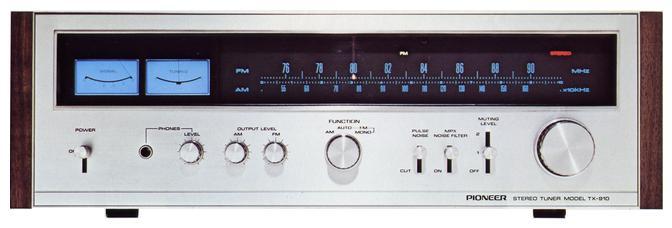
Pioneer TX-910
¥ 75,000 (around 1973)
Commentary
FM/AM tuner with PLL circuit in MPX section.
The FM front-end uses a dual-gate MOS FET for the two stage RF amplifier and mixer stage.
Since the dual-gate MOS FET with a low noise figure is used, the practical sensitivity is improved, and the interference rejection capability is improved by the tuning circuit using 5 series variable capacitor.
The local oscillator circuit of the TX 910 is equipped with a buffer circuit. Even when stations with high electric field strength are adjacent to each other, the buffer circuit works to prevent the lead-in phenomenon.
The IF section uses a monolithic IC instead of conventional transistors. The circuit consists of three single-stage differential ICs and one 3-stage differential IC, providing high stability and limiters.
In addition, various characteristics have been improved by combining with wide-band ratio detection.
The filter element is composed of a ceramic filter (4 pieces of 2 elements) with less phase distortion and sharp selectivity characteristics.
This reduces distortion in a wide range within the pass band and improves MPX separation.
A PLL circuit is introduced into the MPX section.
The MPX demodulation signal obtained by the PLL circuit is a square wave whose phase always matches that of the pilot signal. Therefore, when it is passed through a double-balanced differential demodulation circuit, the leakage of the demodulation signal is canceled out and hardly appears on the output side, and the leak carrier is small even as it is, and the distortion generated during demodulation is minimized.
Also, since there is no SCA beat interference, the SCA filter can be omitted, which greatly improves the high-frequency separation.
A part of 19 kHz derived from the PLL is used to guide the signal to another phase comparator, which detects the magnitude of the pilot signal and guides the 38 kHz demodulated signal to the demodulation circuit only when the broadcast being received is stereo. When the signal is mono or when the stereo broadcast transmission is too weak for practical use, the circuit is automatically switched to mono and the indicator flashes simultaneously.
The ICPA 1310 has a built-in PLL circuit, a double-balanced differential demodulation circuit, an indicator circuit, and auxiliary circuits such as automatic switching.
It is equipped with a low-pass filter that cuts the 19 kHz pilot signal and the 38 kHz carrier leak during MPX demodulation. This filter eliminates adverse effects such as beat interference and intermodulation during FM recording.
The muting circuit can be switched between two operation levels.
The first stage is used to cut out inter-station noise during channel selection, and the second stage is used to receive only strong stations.
In order to perform accurate muting operation, MOS IC and IC developed exclusively for muting are adopted. In addition, pop noise is suppressed by double action combining lead relay.
It is equipped with a pulse noise suppressor that cuts out the pulse noise caused by Radio noises from automobiles and motorcycles.
It detects both AM noise, which occurs when the limiter is receiving a weak station, and FM noise, which cannot be removed by the limiter circuit, and operates in either case, so it works effectively over a wide range of electric field strength and noise types.
Equipped with a signal meter whose linearity is improved by the AGC circuit, it is not saturated even in a strong electric field region.
In the AM tuner section, a frequency number line type varicon is also used for the AM section to make channel selection easier. In addition, a one stage synchronous RF-amplifier using a 3-row varicon is used to increase interference rejection capability.
In addition, stability and reliability are improved by adopting a high-integration IC. Each amplifier stage is equipped with a sufficient AGC to keep the detection output constant and suppress the occurrence of distortion due to saturation at strong input.
The mixer stage employs a balanced type mixer to improve spurious characteristics.
There are two types of output terminals, fixed and variable.
The output level of the variable terminal can be adjusted independently by FM and AM.
We use a Darlington OTL amplifier as an amplifier for headphones.
Volume can be controlled on the front panel.
It is equipped with a multi-pass terminal, and the best point in the antenna direction can be easily determined by connecting a stereo display SD-100 or an oscilloscope.
.JPG)
.JPG)
.JPG)
.JPG)
.JPG)
Model Rating
| Type | AM/FM stereo tuner |
| FM Tuner Section | |
| Circuit system | MOS FET RF2-stage, 5-series variable capacitor differential 6-stage limiter PLL MPX Demodulator |
| Practical sensitivity (IHF) | 1.5 μ V |
| Capture Ratio (IHF) | 1dB |
| Effective selectivity (IHF) | 90dB |
| Signal-to-noise ratio | 75dB |
| Image Interference Ratio (82 MHz) | 110 dB or more |
| IF Interference Ratio (82 MHz) | 110 dB or more |
| Spurious interference ratio | 110 dB or more |
| AM suppression ratio | 65dB |
| Harmonic distortion factor | Mono : not more than 0.2% Stereo : 0.3% or less |
| Frequency response (stereo) | 20 Hz to 15 kHz + 0.2 -2.0 dB 50 Hz to 10 kHz + 0. 2-0. 5 dB |
| Stereo separation | 1 kHz : 40 dB or more 50 Hz to 10 kHz : 30 dB or more |
| Carrier leak suppression ratio | 65dB |
| Antenna | 300 Ω Balanced Type 75 Ω Unbalanced Type |
| Muting | Two step level switching |
| MPX Noise Filter | ON-OFF |
| <AM Tuner Section> | |
| Circuit system | Tunable RF1-stage 3-train varicon |
| Practical sensitivity (IHF, bar antenna) | 300 μ V/m |
| Practical sensitivity (IHF) | 15 μ V |
| Selectivity | 40dB |
| Signal-to-noise ratio | 50dB |
| Image interference ratio | 65 dB or more |
| IF interference ratio | 85 dB or more |
| Antenna | Ferrite bar antenna included |
| <General> | |
| Output Level / Impedance | Fixed : 650mV/4.7k Ω Variable : 70 mv ~ 2V/300 Ω Headphone : 150 mv (8 Ω) |
| Semiconductor used | Transistor : 33 FET : 6 IC : 8 Diode, etc. : 21 |
| Power supply voltage | 100 VAC, 50Hz/60Hz |
| Power outlet | Power switch not linked : 1 system |
| Power consumption | 30W |
| External dimensions | Width 430x Height 138x Depth 345 mm |
| Weight | 8.9kg |