.jpg)
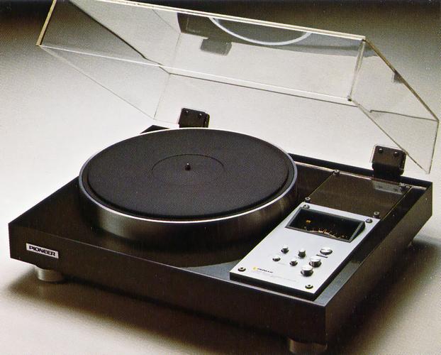
Pioneer XLC-1850
¥ 90,000 (around 1979)
Commentary
Armless player that adopts quartz PLL system.
Universal type arm mounting board is adopted, and domestic and overseas tone arms except for 16 inch long arm can be used.
The mounting board uses laminated plywood with a metallic finish for easy drilling.
The turntable uses a direct drive system, and the motor shaft directly drives the turntable without passing through a transmission mechanism.
A high-torque brushless DC servo hole motor is used hole motor.
The magnetic pole switching (switching circuit), which greatly influences the performance of the DD motor itself, adopts a brushless type using three Hall elements developed by Pioneer's original manufacturing method, and realizes high S/N and reliability.
The XLC 1850 uses a quartz PLL system for the servo circuit with high detection accuracy. By comparing the output pulse of the generator attached to the rotating shaft of the motor with the pulse of the reference signal using a crystal, not only the frequency difference between the two is detected, but also the phase difference (time difference between lead and lag) is detected and the rotation speed is controlled. This enables accurate detection of long and weak speed changes that were considered difficult to detect with conventional methods, and always maintains the correct rotation speed.
In place of the conventional strobe, a direct-reading pitch indicator is used to indicate the rotational speed during fine adjustment of speed.
Since the deviation from the exact number of revolutions can be read directly in numerical values, it is easy to compare and play records at the same pitch and to confirm when the pitch of a record matches the pitch of an instrument.
When the Quartz Lock is ON, this indicator is synchronized with the correct rotation speed with the word "Quartz" lit. When the brake is applied by an external force, the lamp goes out. When the Quartz Lock is OFF, the memory of the pitch indicator lights. The rotation speed of the turntable is measured by a combination of a Schmidt circuit and an integrating circuit for driving the meter, and the rotation speed can be displayed in analog form.
The volume for fine adjustment has a special resistance curve so that it can turn in the same sense as the indicated angle of the meter at the time of adjustment, taking usability into consideration.
Equipped with quick stop mechanism for electronic devices.
In this system, when the stop button is pressed, the control circuit switches to generate torque to rotate the motor in the opposite direction and applies the brake rapidly. When the rotation is almost stopped, the power is turned off and the turntable stops.
This drive circuit responds quickly when the motor speed is increased by electronic braking, and when the speed is changed from 45 rpm to 33 1/3rpm, servo is also activated and constant speed rotation is achieved immediately.
By integrating the control circuit and drive circuit into an IC, unstable elements that cause performance degradation are eliminated.
A bipolar IC is used for the drive circuit and a MOS IC is used for the control circuit.
The cabinet is made of aluminum die cast with a thickness of 4 mm and a weight of 4.7 kg, and has a structure to prevent howling by analyzing resonance mode.
The cabinet has a box structure with 24 ribs around it. In addition, a new material with low Q (low resonance) is used for the bottom cover. In addition, an insulator made of a combination of special rubber and die-cast solid is directly attached to the cabinet body howling margin by 3 db.
A cut-core transformer is used for the power supply.
The cut-core transformer has low leakage flux and excellent regulation. By floating mounting the transformer on the cabinet board, the effect of noise on sound quality is suppressed.
A push type is used for the operation part.
Concentrated layout on a single die-cast panel enables one touch operation.
A removable transparent acrylic dust cover is used for the dust cover.
Comes with one touch universal arm rest.
Installation is one touch type and can be installed in any position by adhesive tape at the bottom.
.jpg)
.jpg)
.jpg)
.jpg)
Model Rating
| Type | Record player |
| Drive system | Direct drive |
| Drive motor | Quartz PLL brushless DC servo hole motor |
| Turntable | 32 cm Aluminum Die-cast |
| Inertial mass | 350kg-cm2 |
| Number of revolutions | 33 1/3, 45 rpm |
| Fine adjustment of rotation speed | + / - 6 per cent |
| Uneven rotation | 0.025% or less (WRMS) |
| S/N | 63 dB or More (JIS) 75 dB or more (DIN-B) |
| Load variation | 0% (Needle Pressure 120g or Less) |
| Start-up characteristic | 1/2 Rotation |
| Rotational speed deviation | ± 0.002% |
| Drift | Time drift : not more than 0.0003% / h Temperature drift : 0.00004% / ℃ or less |
| Attachment mechanism | Pitch indicator Height Adjustable Insulator Transparent Acrylic Dust Cover (Free Stop Hinge) Electronic quick stop mechanism |
| Cabinet | Aluminum Die-cast Cabinet |
| Semiconductor used | IC : 5 Transistor : 2 Diode : 4 pcs Hall element : 3 pieces |
| Pwer | 100 VAC, 50Hz/60Hz |
| Power consumption | 12W |
| External dimensions | Width 490x Height 185x Depth 406 mm |
| Weight | 14kg |
| Attachment | EP Adapter Hexagonal adapter Arm mounting instruction paper Arm Mounting Panel for SME 3009/SII Universal arm rest |
.jpg)
1. Magnetic pulse detection type frequency generator
A magnetic pulse is magnetized on the lower surface of the rotor magnet (rotor magnet), and an AC signal (voltage) corresponding to the rotational speed of the motor is taken out by the speed detection board attached facing the pulse.
2/3. Phase comparator, frequency comparator
The AC signal obtained from the generator is amplified, passed through a waveform shaping, synthesis and multiplication circuit, and compared with the reference signal passed through a speed switching / dividing circuit. The control voltage corresponding to the phase difference is detected and converted into a DC signal, which is then combined with the output of the comparator and sent to the control circuit. This ensures phase lock and ensures accurate servocontrol. The comparator is also in parallel with the phase comparator to improve the transient characteristics of the motor and other characteristics of the PLL loop.
4. Bidirectional discrimination circuit and comparison control circuit
It detects the magnitude of the combined output of each signal and the direction of the control output (acceleration / deceleration), amplifies the control signal accurately and quickly, and transmits it to the bidirectional drive circuit.
5. Bi-directional drive circuit
The current is supplied to the motor according to the control signal applied by the control circuit and the position signal synthesis circuit. In this case, the control torque acts in both directions of acceleration and deceleration. Therefore, the motor has excellent responsiveness such as transient response to changes in motor speed due to disturbance and switching time for rotational speed.
6/7. Position detection unit and position signal synthesis circuit
Three Hall elements are arranged inside the motor with an electrical phase angle of 120 °. These Hall elements generate signal voltages sequentially by the rotation of the motor and are synthesized into predetermined signals by the position signal synthesis circuit to switch the transistors of the bidirectional driving circuit (winding current switching operation).
8. Reverse rotation prevention circuit
Although this circuit is not related to normal operation, it functions as a protective circuit to ensure normal operation even if it is forcibly rotated backward by hand.
9. Crystal oscillator
It generates a reference signal that controls the number of revolutions of the phono motor. It uses a crystal resonator that is less affected by temperature and humidity and less subject to aging. It compensates for minute frequency differences precisely with a trimmer capacitor, making it a highly stable and accurate circuit.
10. Frequency Divider Circuit
The crystal oscillator uses a higher frequency (3,072 MHz) than is actually used in consideration of more stable operation and rationality, and is divided to 6 kHz.
11. Speed variable sub oscillator
If you want to change the pitch of the playback section, you need to change the reference frequency. When the quartz lock is off, the motor rotation is synchronized with the frequency of this circuit.
12. Rotation Speed Detection Circuit
The rotational speed comparison signal obtained by the frequency generator is inverted by a circuit with high input impedance so as not to affect the signal of the motor. After the level adjustment, it is converted into a DC signal by a low-pass filter and sent to the meter drive circuit.
13. Meter drive circuit (operates only when lock is OFF)
A differential amplifier consisting of two operational amplifiers compares the level of the DC signal obtained by the rotation speed detection circuit and drives the meter.
14. Lock determination circuit (operates only when quartz lock is ON)
The output of the differential amplifier in the meter drive circuit is passed through a circuit that performs an analog OR operation to determine whether the instrument is locked.
15. Start-stop, flip-flop circuit
When the Start / Stop button is pressed, the flip-flop circuit changes to 2 states (H/L) and issues an instruction to the AND circuit as well as ON-OFF of each oscillator. The flip-flop circuit is always set to the STOP state when the power supply is only ON.
16. Stop Detection Circuit
The rotational speed comparison signal obtained by the frequency generator of the motor is input to the Schmidt circuit to detect the rotational stop.
17. AND Circuit
The AND circuit turns off the power supply circuit only when the flip-flop circuit is in the stop state and the stop detection circuit is output.
.jpg)
・ When the power switch is turned ON, the flip-flop circuit is always set to the STOP side, so the meter will light but the motor will not turn.
・ When the start button is pressed, the flip-flop circuit inverts, the AND circuit works, the power is turned on, and the motor rotates.
・ When the stop button is pressed, the flip-flop circuit is inverted again, and a stop instruction is issued to the AND circuit and the reference oscillation frequency is stopped. Since the reference frequency becomes 0 Hz, the signal is sent to the bidirectional driving circuit so that the reverse torque is generated by the control circuit and the control direction indicating circuit, and the frequency of the frequency generator is lowered.
・ When this frequency becomes almost 0 Hz, the AND circuit operates according to the stop detection instruction, the motor power supply is turned off, and the rotation stops completely.
.jpg)
Schmitt trigger circuit
The level of the AC waveform that is proportional to the number of revolutions of the motor from the frequency generator is adjusted to a certain height so that when frequency-voltage exchange is performed by the integrator circuit, a voltage that is accurately proportional to the frequency is output.
Integrating circuit
This is an F-V (frequency-voltage) converter that converts AC voltage with a frequency proportional to the number of revolutions of the motor into DC voltage proportional to the number of revolutions of the motor.
Differential amplifier circuit
The DC voltage, which is proportional to the number of revolutions of the motor and is exchanged by the integrator circuit, is compared with the reference voltage by this circuit. If the voltages A and B in the figure are equal, the motor is at the specified number of revolutions, the voltage to the meter is 0, and the meter shows a center speed deviation of 0. If the number of revolutions of the motor is higher than the specified number of revolutions, the voltage of A is higher than B, the voltage of A-B is amplified by a differential amplifier circuit, a + voltage is added to the meter, and the meter shows a + direction, and vice versa if the number of revolutions of the motor is lower than the specified number of revolutions.
.jpg)
.jpg)