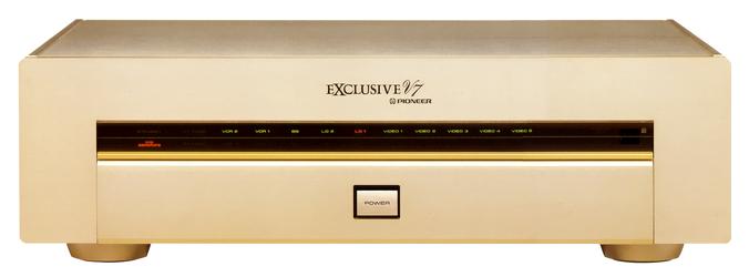
Exclusive V7
¥ 480,000 (around 1992)
Commentary
A video selector developed to achieve 0 video transmission error.
Ten input terminals are installed for each of composite and S-video.
There are two monitor outputs for composite and S-image, and four Rec outputs for composite and S-image.
The input switch is a semiconductor switch and uses a relay input switch to reduce distortion caused by the switch. The video amplifier uses a video amplifier IC that ensures low distortion, high S / N ratio and broadband frequency characteristics.
In order to prevent signal interference between connected devices through the ground side, we have adopted a separate ground circuit that turns on/off not only the hot side but also the ground side simultaneously. This ensures that noise from other connected devices flowing in from the ground side is cut off, and the purity of the video signal is increased.
Video and S-Video systems, power supply and Y/C separation circuit are laid out independently to eliminate mutual interference between circuits.
In addition, a shield plate is used to separate the input signal switching section from the output video amplifier section to improve isolation. In addition, a shield wire is used for the signal path, and part surfaces of double-sided boards are used for shielding to eliminate various effects of signal contamination.
In addition, by using carefully selected parts, the video signal transmission error is suppressed.
It is equipped with a Y/C separation circuit that separates luminance and color signals from the composite signal of devices that do not have S-video output. It is also equipped with a Y/C separate memory function that can store the on/off status of the Y/C separation circuit according to the connected device for each input selector.
In addition to input switching and power on/off, it comes with a system remote controller that enables control amplifier C7 volume, function switch switching and power on/off.
For connection with C7, the control signal is converted into an optical signal by a photocoupler and transmitted in order to cut the effect of the loop, thereby eliminating interference between video and audio signals.
.JPG)
.JPG)
.JPG)
.JPG)
Model Rating
| Type | Video selector |
| Composite input terminal | Video1, 2, 3, 4, 5, LD1, 2, VCR1, 2, BS : 1Vp-p/75 Ω |
| Composite output terminal | Output1, 2, VCR1, 2, Video3, 4 Rec out : 1Vp-p/75 Ω |
| S input terminal | Video1, 2, 3, 4, 5, LD1, 2, VCR1, 2, BS Luminance Signal : 1Vp-p/75 Ω Color Signal : 0.286Vp-p/75 Ω |
| S output terminal | Output1, 2, VCR1, 2, Video3, 4 Rec out Luminance Signal : 1Vp-p/75 Ω Color Signal : 0.286Vp-p/75 Ω |
| Isolation | 63dB(3.58MHz) |
| Frequency characteristic | DC ~ 40 MHz + 0 -3dB |
| D.G | 0.2% |
| D.P | 0.2 ゜ |
| Signal-to-noise ratio | 63dB |
| Maximum input level | 2Vp-p |
| Power supply voltage | 100 VAC, 50Hz/60Hz |
| Power consumption | 30W (Electrical Appliance and Material Control Law) |
| External dimensions | Width 460x Height 140x Depth 374 mm |
| Weight | 12.8kg |
| Attachment | Wireless Remote Control |