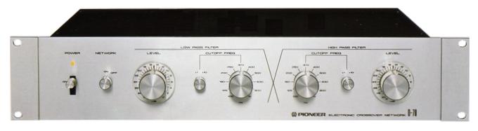
Pioneer D-70
¥ 45,000 (around 1980)
Commentary
A simple two way electronic crossover network designed for ease of use.
The high-pass filter part of the buffer amplifier uses a pure complimentary service class A SEPP circuit with two positive and negative power supplies (± 31 v) excellent in high-frequency characteristics.
Even harmonic distortion, which accounts for most of the distortion components, is canceled by the complimentary service circuit and operates at low distortion.
In addition, by increasing the input impedance and decreasing the output impedance, it is designed not to affect the CR element of the filter.
The low-pass filter consists of three stages. The first stage employs a pure complimentary service class A SEPP circuit with two positive and negative power supplies (± 31 v), the same as the high-pass section. The second stage employs a pure complimentary service class A SEPP circuit with two positive and negative power supplies, and the last stage employs a pure output class A SEPP circuit with two positive and negative power supplies.
The condenser of the filter circuit uses elements with low loss and leakage current, such as a styrene condenser with an error of 2%, to improve the accuracy of frequency characteristics, sound rise and crossover frequency.
There are 11 cut-off frequencies for the position of magnification x1 and 11 cut-off frequencies for the position of magnification x10. Even if overlapping frequencies are considered, 21 cut-off frequencies can be selected in increments of 1/3 octave.
The cutoff slope is 12dB/oct, and a filter with linear slope characteristics up to an attenuation of -80dB (1 / 10,000 voltage) or less is used.
The cut-off frequency switch is independent of the low-pass or high-pass mode, so it is possible to overlap the crossover between woofer and tweeter.
The level control is a 32-position, a 32-position, 1-dB-step attenuator.
The memory marker allows you to accurately reproduce the original level even if you move the level you set once.
When the network switch is turned off, the signal from the preamplifier can be output to the low-pass Variable jack as it is.
Rack mount adapter that can be mounted on separately sold EIA standard rack, JA-R2S and JA-R1S is included (2U).
Also, if you remove the Adapter part, the width will be the same size as the 20th series.
It uses a design that matches with Pioneer's Separate Amplifier No. 70 series.
.JPG)
Model Rating
| Type | Electronic crossover network | ||||
| Circuit system |
|
||||
| Cutoff frequency | Low pass, high pass x1 position : 100, 125, 160, 200, 250, 320, 400, 500, 630, 800, 1 kHz x10 positions : 1k, 1.25k, 1.6k, 2k, 2.5k, 3.2k, 4k, 5k, 6.3k, 8k, 10 kHz |
||||
| Slope characteristic | 12db/oct | ||||
| Level control | 0 ~ -30dB (1 dB step), - ∞ | ||||
| Insertion loss | 0 to -2dB | ||||
| Input impedance | 40k Ω | ||||
| Output impedance | 3k Ω (MAX) | ||||
| Output (RL : 50k Ω) | 1 v, 8 v (MAX) | ||||
| Harmonic distortion factor (20 Hz to 20 kHz) | 0.003% (1 V Output) 0.01% (8 v Output) |
||||
| Frequency Response (Low End/High End) | 5Hz/500kHz +0 -1dB | ||||
| SN ratio (at 1 V output) | 100 dB (IHF, A-network, short circuit) | ||||
| Semiconductor used | Transistor : 46 Diode, other : 36 pcs |
||||
| Power supply voltage | 100 V, 50Hz/60Hz | ||||
| Power consumption (Electrical Appliance and Material Control Law) | 11W | ||||
| External dimensions | Width 480x Height 94x Depth 347 mm (includes rack-mount adapter) | ||||
| Weight | 5.9kg | ||||
| EIA standard rack mounting unit | 2U |