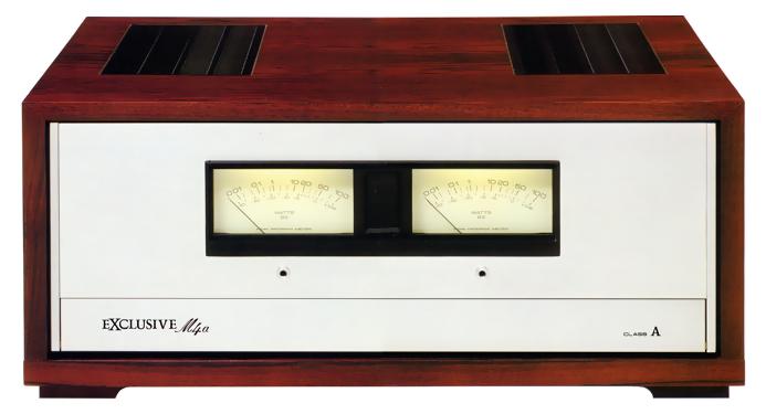
Exclusive M4a
¥ 430,000 (around 1981)
Commentary
This is a stereo power amplifier that achieves high-quality sound in a class-A amplifier circuit.
The input stage of the differential amplifier drives the push-pull pre-driver stage and drives the final stage of 8 power transistors (4 parallel connection) per channel.
A class A push-pull circuit is excellent because it has no notching or crossover distortion. Therefore, there is little distortion when NFB is not applied. Moreover, it has excellent stability and transient characteristics especially in the low frequency range because the power supply does not vary depending on the power.
We have developed and used special specifications for each sound quality part, such as condensers such as Mylar, STICON and electrolytic capacitor, and non-inductive wound non-magnetic resistor.
In order to minimize distortion, oxygen-free copper wire is used as wiring material.
The substrate is a 140 μ m thick copper foil glass epoxy substrate.
While conventional glass epoxy boards were used by attaching 35 μ m copper foil, we have adopted 140 μ m copper foil, which is four times larger than conventional ones, in order to reduce DCR (direct current resistance) and inductance in the board.
In order to ensure stable performance and reliability, all input / output terminals and assembly terminals are gold-plated to greatly improve the conduction characteristics.
In the past, nickel plating was applied to the base layer in order to stabilize the plating. However, since nickel is ferromagnetic, distortion caused by hysteresis occurred.
The newly developed pin jack used in the M4a has been plated on a non-magnetic substrate with stability equal to or better than that of nickel, preventing distortion and obtaining stable contact performance.
The power cord is double-insulated, high reliability and large capacity (15A) power cord.
In addition, the core wire of the power cord is colored white and black, and the connection with the AC plug is managed to unify the polarity.
The connection code uses a oxygen-free copper wire as the material and a gold-plated plug made of non-magnetic material as the pin plug to minimize the occurrence of strain in the connection code. The connection code structure is different from the conventional coaxial structure in that it uses a star quad system in which opposing core wires of the signal wire are twisted together to reduce inductance. In addition, the signal wire is completely shielded by a conductive polymer material and braiding.
As a result, it is possible to transmit high-quality signals with low distortion and low loss.
To cope with the heat generated by a class A amplifier, the chassis is configured to form a cooling duct. Two fans installed in the lower part of the cabinet are used for forced-air cooling. In addition, the fan is operated at low voltage and low speed to suppress the rotational noise.
In addition to the conventional output point DC potential detection circuit which combines a relay and an electronic circuit, a thermal detector using a positive star and a protective circuit using a thyristor are added.
.JPG)
.JPG)
Model Rating
| Type | Stereo power amplifier |
| Circuit system | Differential 2-Stage, PP Drive, 2-Stage Darlington, Quadruple PP Pure complimentary service OCL (Class A Operation) |
| Effective output (20 Hz to 20 kHz, both channels driven) | 50W + 50W (8 Ω) |
| Harmonic distortion factor (20 Hz to 20 kHz) | 0.01% or Less (Effective Output) 0.01% or Less (at 25W output) 0.01% or Less (at 1W Output) |
| Cross modulation distortion factor | 0.01% or Less (Effective Output) 0.01% or Less (at 25W output) 0.01% or Less (at 1W Output) |
| Output Bandwidth (IHF, both channel drives) | 5 Hz to 100 kHz (Harmonic Distortion Factor 0.05%) |
| Frequency response (at 1W output) | 3 Hz ~ 60 kHz + 0 -1dB |
| Input Sensitivity / Impedance | Input1, 2 : 1 V, 2V/50k Ω |
| Output terminal | Speaker : 8 Ω |
| Damping factor (20 Hz to 20 kHz, 8 Ω) | 30 or more |
| Subsonic filter | 8 Hz, 6dB/oct. |
| S/N (IHF, A-network, short circuit) |
110 dB or more |
| Semiconductor used | Transistor : 59 IC : 6 Diode, etc. : 67 pcs |
| Power supply voltage | 100 VAC, 50Hz/60Hz |
| Rated power consumption (maximum power consumption) | 320W (Electrical Appliance and Material Control Law) |
| Power outlet | Power switch not linked : 1 system |
| External dimensions | Width 468x Height 206x Depth 385 mm |
| Weight | 27.3kg |
| Attachment | Relay cord with pin plug |