Exclusive M3
¥ 315,000 (around 1975)
Commentary
In order to create a truly high-quality product, it challenges the limit of possibilities based on the essence of audio. From the assembly of parts to the final adjustment, it is carefully hand-made and completed in high dimension.
The input circuit uses a two stage differential amplifier as a balanced amplifier. The driver stage is driven by a pre-driver of class A push-pull circuit. In addition, a circuit system is adopted that leads to a power stage of triple push-pull with good linearity even at large current.
The entire circuit maintains the minimum amount of NFB by adjusting the gain optimally and improving the non-NFB characteristics through local current feedback.
In addition, the class A PP circuit of the pre-driver stage is perfectly balanced in DC, and it is effective for low distortion factor and improvement in start-up characteristics.
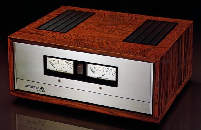
It is equipped with a peak power meter that can directly read the peak output level of music as a power value. By adopting a logarithmic compression circuit, the scale can be directly read from 0.01W to 200W (-40dB to + 3 dB) without changing the sensitivity.
The meter uses a large external magnetic type meter that rises quickly and has good damping, so that the indicator can be moved to an easy-to-see position even at low volume.
Glass epoxy boards with high strength and reliability are used for printed circuit boards.
In addition, the volume for the level control of the speakers is a sealed communication type. In addition, highly accurate and highly reliable parts are carefully selected for each resistance from the transistor.
The power supply section uses a large cut core power transformer and a 33,000 μ Fx2 power capacitor with low leakage flux and excellent regulation.
The speaker jacks are installed Route 3, and each system is equipped with level control.
The protection circuit is divided into two functions.
One protects the speaker when a DC voltage is generated at the output, and also serves as a power muting. The other protects the amplifier from damage due to overcurrent caused by a load short-circuit, etc., by detecting a trouble and limiting the input.
In both cases, the sensing circuit quickly detects movement and reliably protects circuit components and speaker systems.
To prevent a surge current when the power switch is turned on, we use a surge current prevention circuit that uses a relay to limit the current when the switch is turned on and returns to normal operation after a few seconds.
The input sensitivity can be selected from 1 v or 2 v depending on the output of the preamplifier using the front panel selector switch.
The subsonic filter has a built-in CR type that can be turned on and off as needed.
Attached is the measured value of each unit.
.JPG)
.JPG)
.JPG)
Model Rating
| Type | Stereo power amplifier |
| Circuit system | Differential 2-stage PP Drive 3-Step Darlington Triple PP Pure complimentary service OCL system |
| Effective power | 150W + 150W (8 ω, 20 Hz to 20 kHz, B.C. D) |
| Harmonic distortion factor | 0.1% or Less (at Rated Output) |
| Output bandwidth | 5 Hz to 35 kHz |
| Frequency characteristic | 10 Hz to 80 kHz + 0 -1dB |
| Damping factor | 35 or More (8 Ω) |
| Input sensitivity | Input1, 2 : 1 v, 2 v |
| Subsonic filter | 8 Hz, 6dB/oct. |
| Speaker level control | For A, B, and C : 0 to -20dB |
| Peak meter indication range | 0.01W ~ 200W (-40dB ~ + 3 dB) |
| Semiconductor used | Transistor : 84 IC : 6 Diode : 82 Pieces |
| External dimensions | Width 468x Height 206x Depth 370 mm |
| Weight | 27kg |