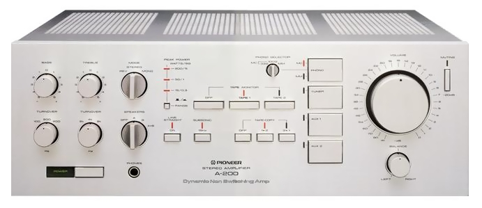
Pioneer A-200
¥ 169,000 (released in 1982)
Commentary
This pre-main amplifier was developed with the theme of high quality and dynamic range of the amplifier itself.
By adopting dynamic power supply system and non-switching circuit, the concept of real dynamism is reflected in the overall to realize high power with high quality.
A dynamic power supply system is used for the power supply part in order to cope with a wide dynamic range of the source and to make the speaker sound as much as possible even at large input.
In this system, low voltage section (VL) and high voltage section (VHThe power supply circuit drives only the low-voltage part at the normal signal level and drives only the high-voltage part at the time of Tsutomu Dainyu. This greatly reduces the loss at the output-stage and enables high power.
In addition, the high voltage section always follows the signal waveform with a constant voltage value, so that no waveform loss occurs.
In addition, when a large signal repeatedly enters over a wide area, the high-voltage section remains locked as long as the signal continues. This design prevents waveform loss due to delay.
The transformer employs a large toroidal transformer characterized by low flux leakage and high regulation. Eight electrolytic capacitors are installed for a total capacitance of 176,000 μ F. We have achieved a low impedance. In addition, we use non-magnetic parts such as copper lead wires and oxygen-free copper wires in the power supply to eliminate harmful magnetic distortion.
The power section is equipped with an established non-switching circuit that realizes 0 switching distortion.
Pioneer's proprietary high-speed bias servo circuit controls the bias current according to the input signal to keep the transistor in operation at all times. As a result, music contamination caused by switching distortion is fundamentally suppressed.
An FET buffer circuit is adopted between the voltage and power amplifiers to completely separate the voltage and power amplifiers, greatly improving the bare characteristics before applying NFB.
The input impedance of the FET is close to infinity, and even if the power amplifier receives load impedance fluctuations due to its nature, the effects do not appear on the input side. Moreover, the operation of the voltage amplifier is stable and the power amplifier can be driven with low output impedance (constant voltage drive). Therefore, the generation of distortion due to the nonlinearity of the power amplifier is suppressed, the effect of reaction signal from the speaker is eliminated, and the distortion factor of the power unit is further reduced.
The MC head amplifier has a push-pull configuration from the input to the output. In addition, the input is parallel push-pull with ultra-low-noise FET. The feedback point of the DC servo is not the first stage but the second stage bias power supply so that the servo circuit does not affect the SN ratio.
As a result, the S / N ratio is 74 dB, which is close to the theoretical limit of 76 dB due to the thermal noise of transistors in this circuit system.
DC servo circuits are used for each of the MC head amplifier, equalizer amplifier, and power amplifier.
As a result, all coupling capacitors from the MC input to the speaker output have been removed, and all stages have been switched to non-coupling capacitors. This eliminates the need to worry about the coloring of sound caused by capacitors, and realizes high-resolution sound quality.
It is equipped with a line straight switch which can obtain high quality sound by directly connecting an equalizer amplifier and a power amplifier.
Passes tone controls, modes, and balance volumes to simplify the signal path.
Non-magnetic parts are used to suppress the magnetic distortion that adversely affects the sound quality and to obtain more pure sound quality.
Copper lead wires are used for all semiconductors used in each amplifier stage, and copper is also used for lead wires and caps for main resistors such as emitter resistors.
We also use copper-based lead wires for main capacitors and oxygen-free copper wires for main wiring materials.
The chassis is plated with copper and has an H-shaped structure to prevent frame noise.
In addition, the Lch and Rch of the power amplifier are independent, the large signal system and small signal system are separated, and the equalizer amplifier and MC head amplifier are all structurally cut off to prevent mutual interference.
An extremely thick power cord with double insulation structure is used for the power cord.
We also pay attention to the fact that sound changes depending on the polarity of the AC line, and thoroughly control the winding method of the transformer and the polarity of the power cord.
.JPG)
.JPG)
.JPG)
.JPG)
Model Rating
| Type | Pre-main amplifier |
| Effective power | 200W + 200W (20 Hz to 20 kHz, double-channel drive, 8 Ω) |
| Harmonic distortion factor (20 Hz to 20 kHz) | 0.002% (at effective output) |
| Intermodulation distortion factor (50 hz : 7 khz = 4 : 1) | 0.002% (at effective output) |
| Output bandwidth | 5 Hz ~ 65 kHz (IHF, both channel drive, THD0.01%) |
| Output terminal | Speaker (4 Ω ~ 16 Ω) : A, B, A + B Tape Rec:150mV |
| Damping factor | 140 (20 Hz ~ 20 kHz, 8 Ω) |
| Input Sensitivity / Impedance | Phono MM : 2.5mV/50k Ω Phono MC : 0.15mV/100 Ω, 33 Ω, 8 Ω Tuner, AUX, Tape Play1, 2 : 150mV/50k Ω |
| Phono maximum allowable input (1 kHz, THD0.0008%) | MM:300mV MC:18mV |
| Frequency characteristic | Phono MM : 20 Hz to 100 kHz ± 0.2 dB Tuner, AUX, Tape Play : 1 hz to 200 khz + 0 to 3 db |
| Signal-to-noise ratio (IHF, A-network, short circuit) |
Phono MM:90dB Phono MC:74dB Tuner, AUX, Tape Play : 115 dB |
| Tone control | Bass : ± 6 dB (100 Hz) Treble : ± 6 dB at 10 kHz |
| Filter | Low : 15 Hz, 6dB/oct. |
| Power supply voltage | 100 VAC, 50Hz/60Hz |
| Power consumption (Electrical Appliance and Material Control Law) | 360W |
| External dimensions | Width 420x Height 150x Depth 420 mm |
| Weight | 19.0kg |