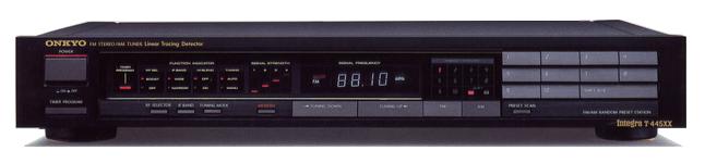
ONKYO Integra T-445XX
¥ 43,000 (released in 1986)
Commentary
FM/AM tuner using W stabilizer system.
In order to achieve even higher levels of reception performance and sound quality, which are the development themes for the Integra tuner, we developed and installed a W stabilizer system.
The W stabilizer method is an improved method using two stabilizers, an electrical D. R (Direct Receiving) stabilizer and a mechanical X stabilizer. In both electrical and mechanical aspects, the W stabilizer method pursues low distortion and stability of the tuner circuit.
The D. R stabilizer is a circuit developed to directly receive a wide dynamic range source such as CD. The I. D. S (Isolated Digital System) and D. C. I (Distortion Correcting IF System) reduce digital noise generated inside the tuner to obtain high S/N ratio and achieve high selectivity and low distortion rate.
The X stabilizer is made of a special alloy of PbSb. It is the most susceptible to speaker vibration and mechanically suppresses the local vibration that causes the music signal to become muddy.
In the I. D. S, the digital and analog sections are separated during broadcast reception by automatically switching between the PLL mode required for receiving and the mode required for listening to the broadcast, thereby reducing digital noise and improving S/N.
L. T. D (Linear Tracing Detector) is used for the detector.
This system directly detects 10.7 MHz signals. It is a closed-loop system in which signals delayed by 90 ° from the IF signal are detected by tracing the IF signal linearly. Therefore, S/N is good.
Using a D.C. I circuit that compensates for the distortion generated by the IF filter while maintaining a selectivity of 60 dB, it achieves a low distortion factor.
The IF stage employs wide/narrow 2-stage switching.
The MPX circuit is simplified using a Digital Computed Decordor (D.C. D).
By creating a pure 38 kHz (sine wave) for left and right separation and using an analog operation method for the input composite signal, there is no generation of harmonics and no need for a filter to improve separation and distortion factor.
The front-end section has been designed to improve intermodulation by adopting a two stage series buffer from the station and two stage RF switching.
AM/FM random such as AM/FM random 20-station memory, preset scan and 5-station timer program.
.JPG)
Model Rating
| Type | FM/AM Tuner | ||||
| FM Tuner Section | |||||
| Receiving frequency | 76.1 mhz to 89.9 mhz | ||||
| Practical Sensitivity (75 Ω / IHF) | Boost on : 0.9 μ V/10.3 dBf Boost off : 4.0 μ V/23.3 dBf |
||||
| S/N50dB sensitivity (75 Ω / IHF) | 2.0 μ V/17.3 dBf | ||||
| Intermodulation interference ratio (± 1 MHz / ± 2.5 MHz) | boost on:88dB/90dB boost off:103dB/110dB |
||||
| Image Interference Ratio (83 mhz) | boost on/off:90dB | ||||
| IF Interference Ratio (83 MHz) | boost on/off:100dB | ||||
| Spurious interference ratio | boost on/off:100dB | ||||
| Two signal selectivity | wide:60dB narrow:85dB |
||||
| Strain Rate (400 Hz) |
|
||||
| Stereo separation |
|
||||
| AM suppression ratio | wide:62dB narrow:50dB |
||||
| Capture ratio | wide:1.0dB narrow:2.0dB |
||||
| Signal-to-noise ratio | mono:100dB stereo:90dB |
||||
| Frequency characteristic | 20 Hz to 15 kHz + 0.2 -0.8 dB | ||||
| Carrier leak | -65dB | ||||
| Antenna impedance | 75 Ω unbalance | ||||
| Output Voltage (400 Hz) | 500mV(100%) | ||||
| Output impedance | 1.9k Ω | ||||
| <AM Tuner Section> | |||||
| Practical sensitivity | 200 μ V/m (loop antenna) | ||||
| Image interference ratio (999 kHz) | 40dB | ||||
| IF interference ratio (999 kHz) | 57dB | ||||
| 2 signal selectivity (selectivity + / - 10k) | 35dB | ||||
| SN ratio (100mV/m) | 50dB | ||||
| Strain Rate (400 Hz) | 0.3% | ||||
| Output Voltage (400 Hz, 30%) | 150mV | ||||
| Output impedance | 1.9k Ω | ||||
| <General> | |||||
| Power supply voltage | 100 VAC, 50Hz/60Hz | ||||
| Power consumption (Electrical Appliance and Material Control Law) | 17W | ||||
| External dimensions | Width 435x Height 73x Depth 368 mm | ||||
| Weight | 6.1kg | ||||