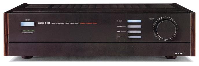
ONKYO Integra P-309
¥ 250,000 (around 1983)
Commentary
A stereo preamplifier developed as the culmination of the "W ・ Super Servo System" which is a further development of the "Super Servo System".
Taking advantage of the characteristics of the super servo system originally developed by Onkyo, the gain of the equalizer amplifier is increased so that it can be used for all cartridges from MM type to MC type without using a head amplifier or step amplifier transformer.
The three units of the MC head amplifier, equalizer and buffer are combined into a single stage type simple equalizer amplifier. It uses a high-current A-class amplifier comparable to a 5W-class output power amplifier, and realizes NF / CR division type equalization in one stage without a buffer amplifier.
In the first stage differential amplifier section, two ultra-low noise and high Gm FETs are thermally coupled in an aluminum case to improve thermal balance and suppress external thermal noise. In addition, S/N is improved by connecting the differential section in parallel to lower impedance. In order to suppress mirror feedback capacitance, this differential amplifier is connected in cascode to expand frequency characteristics.
The second stage differential amplifier and the third stage differential amplifier with current mirror ensure a large naked gain, and by using partial feedback by skillful pole setting, stability and constant distortion factor are realized.
A waiting monitor is mounted on the panel surface.
This monitor detects the temperature of the A-class push-pull transistor at the final stage of the equalizer and the transistor used for the power supply of the equalizer, and displays the stability of the bias after the power is turned on and the operational status of the amplifier with 5-level indicators.
In order to prevent the inductance and resistance of the extension cord, contact resistance at the connection part, crosstalk, etc., W super servo system is adopted.
The W ・ Super Servo system suppresses cross modulation due to unnecessary ultra-low frequencies and equivalently cancels harmful noise components caused by the impedance between the earth and the ground. By using the attached servo sensor code, the distance between the pre-power and the power is electrically reduced to 0 to cancel harmful components.
Direct Tone is a unique tone control method that does not affect the sound quality.
Since it is composed of only passive elements and does not allow harmful capacitors to enter the signal passage path, it can freely correct sound fields without affecting sound quality.
When a power amplifier with low input impedance is connected or when multiple power amplifiers are driven in parallel, problems such as shortage of extremely low frequencies tend to occur. However, by adopting the super servo system, there is no need to insert a capacitor in the output section, and the low-frequency time constant is determined only by the servo circuit, so that shortage of low frequencies is prevented regardless of the load.
As for the power supply, the right and left channels are supplied with completely independent power supplies, and even within the same channel, in order to prevent interference through the power supplies at the front and rear stages, the entire power supply system is designed to be low impedance, and the generation of dynamic modulation (transient intermodulation distortion) is suppressed.
In the IntegraP 309, independent NF type constant voltage stabilizing circuits are used for the left and right sides, and each circuit block is directly connected by a thick copper plate bus (bus) line.
Equipped with a cartridge selector, the optimum load impedance can be switched according to the cartridge to be used.
It is equipped with a recording selector so that the deck is not always connected to part of the circuit even when recording is not done.
You can also record the tuner output while listening to the record.
It has a built-in headphone amplifier so that you can use headphones.
Various filters, muting and input selectors are stored in the kangaroo pocket.
Non-magnetic materials such as copper, aluminum, and brass are used for all necessary parts including the shielding part and all other parts to suppress high-order harmonic distortion caused by magnetic flux.
A self-illuminated one touch selector is used for input switching.
In addition, a method of selecting by a small special audio relay is adopted, and there is no signal wiring.
Equipped with a thermo-coupled register, a register with coupled thermal coefficients is used so that a delicate servo effect is always stably applied to the signal.
.JPG)
.JPG)
.JPG)
.JPG)
Model Rating
| Type | W super servo type stereo preamplifier |
| Input Sensitivity / Impedance | Phono MC : 130 μ V/100 Ω, 330 Ω Phono High Gain MC : 2.5mV/100 Ω Phono MM : 2.5mV/47k Ω, 100k Ω Tuner, AUX, Tape Play : 150mV/47k Ω |
| Output Voltage / Impedance | Tape Rec : 150mV/2.2k Ω Output : 1.5 V, maximum 13V/220 Ω |
| Phono Maximum Allowable Input (THD 0.05%, 1 kHz) | MC:19mV MM, High Gain MC : 380 mV |
| Frequency characteristic | Phono MC : 4 hz to 150 khz + 0. 2-3 db Phono MM : 1.8 Hz to 170 kHz + 0.2 -3dB Tuner, AUX, Tape : 0.8 Hz to 170 kHz + 0 to 3 dB |
| Total Harmonic Distortion Factor (THD, 20 hz to 20 khz, output 3 v) | Phono MC (Volume-30dB) : 0.008% or less Phono MM (Volume-30dB) : 0.002% or less Tuner, AUX, Tape : 0.002% or less |
| Intermodulation distortion factor (SMPTE70Hz : 7 khz = 4 : 1) | 0.003% or Less (at Rated Output) |
| S/N (IHF-A network, input shunt) | Phono MC:70dB Phono MM:88dB Tuner, AUX, Tape : 100 dB |
| Tone Control (Volume-20dB) | Bass : 70 Hz, ± 8 dB Treble : 20 kHz, ± 8 dB |
| Filter | High Cut Filter : 7 kHz, 6dB/oct. EQ Subsonic Filter : 15Hz/20Hz, 6dB/oct |
| Muting | -20db |
| Transient killer operating time | Power on/off:7sec/100msec |
| Semiconductor used | Transistor : 71 FET : 10 IC : 8 Diode : 50 pcs |
| Power supply voltage | 100 VAC, 50Hz/60Hz |
| AC Output | Power link : 2 systems Non-linked : 2 systems Total 1000W (maximum) |
| Power consumption (Electrical Appliance and Material Control Law) | 65W |
| External dimensions | Width 476x Height 122x Depth 415 mm |
| Weight | 10.5kg |