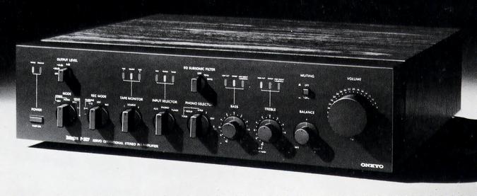
ONKYO Integra P-307
¥ 220,000 (around 1978)
Commentary
A preamplifier that employs the super servo system and direct tone control system.
The newly developed super servo system for the Integra P-307 allows a sufficient margin to smoothly cut infrasound frequencies below 2 Hz in order to prevent harmful phase shift in the range of audibility.
In this circuit system, a monolithic operational amplifier is used for servo operation in each stage, and capacitors are removed from the signal system (coupling and NF loop) in all stages from the input to the output of the MC amplifier.
We have adopted a direct tone control method to further ensure the advantages of the Super Servo method.
The tone control circuit of a general amplifier is inserted between the equalizer amplifier and the tone amplifier and has a gain of nearly 20 dB in case of tone boost. By always having this extra gain, the S/N and distortion characteristics of the tone circuit itself are affected. In addition, a buffer amplifier is inserted after the tone circuit in order to function as an impedance converter, and the characteristics are adversely affected.
The direct tone control uses only an equalizer amplifier and a flat amplifier, and the tone characteristics are associated with the volume control. This realizes a configuration using all passive elements. This eliminates the need for extra gain and simplifies the configuration by eliminating the need for a buffer amplifier.
In actual operation, the effect works in conjunction with the volume control, and usually shows the same change characteristics as the normal tone control. However, when the volume exceeds a certain level, the boost amount of the tone gradually decreases.
The power supplies for the left and right channels are completely independent, and the entire power supply system is designed to be low impedance to prevent interference from the power supply between the front and rear stages, thereby minimizing dynamic modulation (transient intermodulation distortion).
For the P-307, an NF-type constant voltage power supply stabilizing circuit is installed in each channel in order to provide a stable supply of power supply voltage and to make the power supply and distribution lines low impedance. In addition, a high-purity copper plate bus (mother ship) line is widely used, and each circuit block is directly connected directly to the low impedance supply trunk line.
Non-magnetic materials are used for switches, volume bodies and shafts that are easily affected by flux.
In addition, each stage is shielded by a non-magnetic material to prevent mutual interference.
The equalizer amplifier section has a pre-stage cascode FET differential input, one differential stage with a current mirror, and an A-class parallel push-pull configuration for the output stage.
Furthermore, in order to make the RIAA characteristics more precise, the frequency to be corrected for RIAA is divided into two. The NF type is used for the low-boost side and the CR type is used for the high-cut side. In particular, the high-frequency range is corrected with the stable CR attenuation so that there is no degradation of slew rate or blocking, and intermodulation is less.
These two time-constant circuits are specialized in each band, and excellent correction accuracy is obtained in a wide band range of 10 Hz to 100 kHz.
The MC amplifier circuit is switched using a special muting circuit to prevent clicks. The switch mechanism has an OFF position and an electronic delay circuit that mutes the equalizer output to prevent clicks during switching.
In addition, a transient killer circuit that mutes the pre-output and equalizer output when the power switch is turned on, and a break-type read relay that instantly shunt the pre-output to protect the equipment in the subsequent stage in the event of DC leakage.
The flat amplifier section consists of a cascode FET differential input with a current mirror and class A push-pull output. The unique circuit configuration is designed to withstand low impedance loads.
The MC amplifier section is connected with 3-stage FET differential input to achieve low noise.
The output stage is a class A parallel push-pull circuit so that it is less affected by load fluctuation and the distortion in the high frequency range is improved.
We use semiconductor electronic components, various operation switches, panels and knobs, and highly accurate parts that have been carefully examined up to a single screw.
Silver contacts and gold plating are applied to the main switch, relay contacts and phono terminals, respectively.
.JPG)
.JPG)
Model Rating
| Type | Stereo preamplifier | ||||
| Input Sensitivity / Impedance | Phono1, 2 mm : 2.5mv/33k Ω, 47k Ω, 100k Ω Phono3 mc : 120 μ V/220 Ω Tuner, Aux, Tape play1, 2 : 150mV/47k Ω |
||||
| Output Level / Impedance | Tape rec1, 2 : 150mV/2.2k Ω Output1, 2 : 1.5 V (maximum 20 V) / 220 Ω |
||||
| Phono maximum allowable input (THD 0.05%) |
|
||||
| Frequency characteristic | Phono1, 2 : 1.6 Hz to 200 kHz + 0 -3dB Phono3 : 5 Hz to 200 kHz + 0 -3dB Tuner, Aux, Tape play1, 2 : 0.8 Hz to 250 kHz + 0 -3dB |
||||
| Total Harmonic Distortion Factor (THD 20 Hz ~ 20 kHz, Output 3 V) |
Phono1, 2 : 0.005% or less (Vol-30dB) Phono3 : 0.01% or less (Vol-30dB) Tuner, Aux, Tape play1, 2 : 0.005% or less |
||||
| Intermodulation distortion factor (at rated output) | 0.01% or Less (SMPTE 70 Hz : 7 khz = 4 : 1) | ||||
| Signal-to-noise ratio IHF-A Network Input Shunt |
Phono1, 2 : 83 dB Phono3:67dB Tuner, Aux, Tape play1, 2 : 100 dB |
||||
| Tone Control (Volume-20dB) | Bass : ± 6 dB (70 Hz) Treble : ± 6 dB (20 kHz) |
||||
| Filter | High cut filter:7kHz EQ subsonic filter:15Hz/20Hz |
||||
| Muting | -20dB | ||||
| Output level | 0 dB, -10dB, -20dB, off | ||||
| Input-output polarity | All inphase | ||||
| Transient killer operating time | Power on:8sec Power off:100msec |
||||
| Semiconductor used | Transistor : 111 units FET : 10 IC : 14 Diode : 87 pcs |
||||
| Pwer | 100 VAC, 50Hz/60Hz | ||||
| AC outlet | Total up to 1400W Power switch interlock : Route 3 Power switch not linked : 1 system |
||||
| Power consumption | 55W (Electrical Appliance and Material Control Law) | ||||
| External dimensions | Width 450x Height 124x Depth 435 mm | ||||
| Weight | 10.5kg |