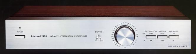
ONKYO Integra P-303
¥ 80,000 (around 1977)
Commentary
A preamplifier with a minimum configuration for high-fidelity transmission.
In order to maintain high fidelity as a transmission system, only one MM, MC, Tuner, Tuner, and Tape is switched as a minimum function necessary for practical use. All adjustment and switching circuits including tone are omitted, and a thin structure suitable for simplifying signal flow is adopted.
If you absolutely need more functions or sound field correction, you can use the Integra U-30 system unit or the Integra E-30 audio equalizer (sold separately) to expand the functions.
The P-303 is designed with attention paid to dynamic modulation (transient intermodulation distortion) caused by interference between functional blocks of the circuit, within the same block, and between left and right channels.
Dynamic modulation, which occurs when a transient signal with a sharp rise is input, such as a music signal, is generated by mutual interference between circuits caused by the impedance of the power supply part and the genetic line. In order to prevent this, the P-303 has low impedance for the power supply and distribution line including the power supply part, and ultra-stable supply of the power supply voltage. It also employs a large number of high-purity multi-spray Bussler in made of copper. A copper plate with a resistance value of 0.0027 Ω / cm is used for the bus earth line, and a copper plate with a resistance value of 0.008 Ω / cm is used for the bus hotline for ± B power supply. The branch of each circuit block is directly connected to the low-impedance supply main line directly, thus suppressing dynamic modulation.
In addition, in order to hold this line in a low impedance over a wide bandwidth, the power supply section employs a double stabilizer circuit with a double supply of a constant voltage power supply, and the capacitors used in the power supply section employ audio signal capacitors with low loss, low leakage, excellent distortion characteristics and temperature characteristics designed especially for audio applications.
The D. L. C. (Dual Line Construction) method completely separates the left and right channels to eliminate interference between the channels. In addition, each block is arranged in a straight line in accordance with the signal path from the input side of the low signal level to the output side of the high signal level to eliminate interference between each block and purify circuit operation.
In addition, the shield case is entirely made of non-magnetic aluminum material, and the MC amplifier in particular is double-shielded.
In all stages of MC amplifier, equalizer amplifier, flat amplifier and buffer amplifier, the linearity is improved by adopting A-class complete vertical symmetrical push-pull system which improves hfe characteristics by combining PNP and NPN.
The differential amplifier section of the first stage differential and 3-stage 8-chip equalizer amplifier uses high-voltage, ultra-low-noise PCT silicon epitaxial transistors (2SC1681, 2SA841). At the same time, the SN ratio is improved by reducing the equivalent noise resistance by making the signal system low impedance.
The RIAA constant circuit has excellent frequency characteristics and transient characteristics, and excellent characteristics are obtained by using G class (capacity deviation within ± 2%) polypropylene film capacitor of non-inductive aluminum foil structure with small tan δ.
The volume control uses a 4-string precision attenuator type volume that can be controlled in conjunction with the front and rear of the flat amplifier to improve the SN ratio when the volume is reduced.
In order to prevent click noise that occurs when the power switch is turned ON/OFF, we have adopted a transient killer circuit using a newly developed break-type lead relay. Instead of being directly connected to the signal circuit as in the past, we have incorporated it into a shunt-type relay to reduce the influence of contact resistance of the relay during normal use.
The MC amplifier section uses a 6-chip low input impedance type that uses ultra-low noise transistors in triple push-pull.
In the flat amplifier section between stages, a wide-band circuit of DC amplifier configuration is adopted in order to completely remove the capacitor in the NF loop.
The first stage differential amplifier circuit employs a dual transistor incorporating two low-noise transistor chips to form a balanced and stable DC amplifier with excellent thermal equilibrium characteristics and a DC amplification ratio of 1 ± 0.02.
A film capacitor with a non-inductive extended foil structure is used for the coupling capacitor to prevent degradation of sound quality.
.JPG)
Model Rating
| Type | Stereo preamplifier | ||||
| Input Sensitivity / Impedance | Phono MC (50 Ω drive) : 100 μ V/10 Ω Phono MM : 2.5mV/30k Ω, 50k Ω, 100k Ω Tuner, Tape play : 150mV/50k Ω Accessory-Rcv : 1.5V/82k Ω |
||||
| Rated Output / Impedance | Tape rec (Phono) : 150mV/12k Ω Accessory-Send : 1.5V/100 Ω Output : 1.5 V (maximum 15 V) / 600 Ω |
||||
| Phono maximum allowable input (THD 0.05%) |
|
||||
| Frequency characteristic | Phono MM (RIAA deviation) : 20 Hz to 20 kHz ± 0.2 dB Tuner, Tape : 3.5 hz to 200 khz + 0 to 1.5 db |
||||
| Total harmonic distortion factor (at 3 v output 20 Hz to 20 kHz) |
Phono MC : 0.03% or less Phono MM : not more than 0.006% |
||||
| Intermodulation distortion factor (at rated output) | 0.01% or Less (SMPTE 70 Hz : 7 khz = 4 : 1) | ||||
| Signal-to-noise ratio (IHF-A network) | Phono MC : 70 dB (input 50 Ω) Phono MM : 83 dB (input shunt) Tuner, Tape : 100 dB (input shunt) |
||||
| Input-output polarity | Phono MC : Reverse Phase Phono MM : Common Mode Tuner, Tape, Acc-Rcv : in-phase |
||||
| Semiconductor used | Transistor : 52 Diode : 29 units |
||||
| AC Output | Switched : Route 3 Unswitched-One system Total:1100VA |
||||
| Pwer | 100 VAC, 50Hz/60Hz | ||||
| Power consumption | 20W (Electrical Appliance and Material Control Law Standard) | ||||
| External dimensions | Width 450x Height 83x Depth 370 mm | ||||
| Weight | 7.5kg |