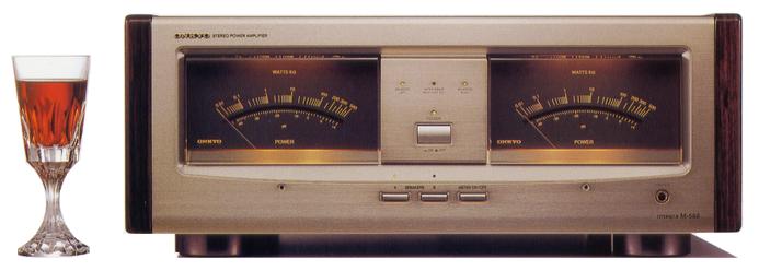
ONKYO Integra M-588
¥ 300,000 (around 1992)
Commentary
Stereo power amplifier with super balance circuit.
It is equipped with a super balance circuit created by combining Onkyo's original double differential amplifier circuit and double super servo circuit. By this, it can handle both balance input and unbalanced input, balance load and unbalanced load without requiring a conversion circuit.
Double Super Servo Technology shifts the reference potential of the output signal so that a constant gain and maximum output can always be obtained even when one of the outputs is grounded.
Not only the power amplifier section but also the input switching, level control and meter circuit are completely independent of each other using twin monoconstruction.
The L/R component layout is completely separated from the center of the chassis to the left and right, and the power amplifier and power supply are separated from the L/R circuit board, so that the characteristics are symmetrical.
To minimize the signal path inside the chassis and keep it ideal, the power supply is located in the front of the chassis to minimize the path from the input terminal to the output terminal and to minimize the negative effect of power supply noise on the small-level signal area.
In addition, there is no input level control at the balance input terminal so that it can be directly connected to a preamplifier, etc. to prevent degradation of sound quality.
The power supply section employs a multi-chemicon system (20,800 μ F per one channel) in which four low-impedance electrolytic capacitors wound with low-magnification foils are connected in parallel in order to improve the power supply response speed characteristics, thereby improving the power supply capability.
In addition, a bridge rectifier diode with a large capacity (15A), approximately 2.5 times larger than the conventional diode, has been adopted for the diode, and the loss is reduced by operating the element with a margin, and the source impedance is kept low.
In addition, a large LASER transformer is placed symmetrically away from the signal system to suppress the interference of leakage flux (magnetic induction).
In addition to laser transformer, the leakage flux is reduced to less than 1/30 by using a modified EI core with a wide outer periphery to reduce the magnetic resistance, a silicon copper plate shield material around the core to provide a tight shield, and an iron case that also serves as a shield.
The peak program meter is used for the fluctuation of the indicator of the power meter, which is controlled so that the rise time is quick and the return time is a little slow. The power display scale can directly read the power at 8 Ω load, and the digital bell display is also available.
In addition, it uses an automatic range adjuster to automatically determine the dynamic range of the music signal and set the power meter pointer to the most readable range.
Based on the x0. 1 range (0 dB = 20W), if the output of the 8 Ω load exceeds 40W (+ 3 dB in the x0. 1 range), the range is instantly switched to the x1 range (0 dB = 200W). After that, if the output does not exceed 40W for several seconds, the range returns from the x1 range to the x0. 1 range.
In addition, when a large input is suddenly input, the range is switched to the x1 range to prevent the meter from shaking out. When the output is small, the range is set to the x0. 1 range.
To achieve complete L/R separation, the meter circuit includes a dedicated circuit for L/R including the power supply circuit.
In addition, L/R is shared only for control circuits requiring synchronization such as range switching, and L/R is electrically separated by optical transmission of control signals.
In addition, in the protector circuit, sensors for detecting overloads and DC component leakage are L/R independent, and optical transmission is performed between common protector circuits to reduce mutual interference between channels.
It uses carefully selected parts, including a custom-made detent volume with sound quality measures such as a carbon resistor with an ultra-low distortion rate of 40 dB, a gold-plated slider, a non-magnetic interstage shield, and a high internal loss brass shaft, a film condenser procured from Germany, a large carbon resistor, a copper foil 70 μ m thick substrate, a gold-plated machined pin jack, and an extremely thick cabtire AC cord.
.JPG)
.JPG)
.JPG)
.JPG)
Model Rating
| Type | Power amplifier equipped with super balance circuit |
| Effective output (20 Hz to 20 kHz) | 300W + 300W (4 Ω) 245W + 245W (6 Ω) 200W + 200W (8 Ω) |
| Dynamic Power (1 kHz) | 750W + 750W (2 Ω) 505W + 505W (4 Ω) 290W + 290W (8 Ω) |
| Total harmonic distortion factor (at rated output, 20 Hz to 20 kHz, 8 Ω) | 0.005% |
| Intermodulation distortion factor (at rated output, 70 Hz : 7 kHz = 4 : 1, 8 Ω) | 0.005% |
| Power Band Wiz (IHF-3dB, THD 0.2%) | 5 Hz to 100 kHz |
| Gain / phase | 32 dB / in-phase |
| Frequency characteristic | 1 Hz ~ 100 kHz + 0 -1.5 dB |
| Input Sensitivity / Impedance | Balanced : 1V/45k Ω (Hot-Cold) Unbalanced:1V/20kHz(Hot-Cold) |
| SN ratio (A-weighted, input short) | 124dB |
| Load impedance | 4 Ω or more |
| Damping factor (8 Ω, 1 kHz) | 180 |
| Meter range switching (automatic) | x1(0dB=200W) x0.01W ~ 50W (0 dB = 20W) |
| Indication range | x1 Range : 0.01W ~ 500W x0.1 range : 0.001W ~ 50W |
| Indication accuracy | 0 ± 1 dB, -10 ± 2 dB, -20 ± 3 dB |
| Power supply voltage | 100 VAC, 50Hz/60Hz |
| Power consumption (Electrical Appliance and Material Control Law) | 550W |
| External dimensions | Width 475x Height 190x Depth 426 mm |
| Weight | 31.0kg |