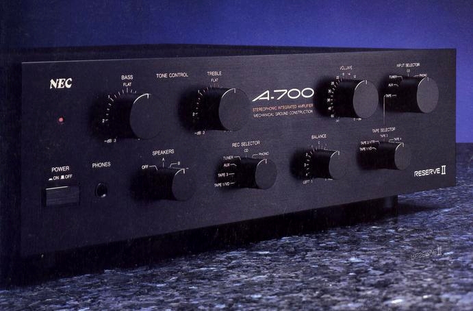
NEC A-700
¥ 79,800 (released in 1985)
Commentary
This is a pre-main amplifier with improved operability for the AV age while applying NEC's original technology such as reserve II power supply.
A push-pull type amplifier circuit is adopted for all amplifier stages and a parallel push-pull configuration is adopted for the final amplifier stage. By using output transistors in parallel, the effective halving due to the emitter resistance entering the output current circuit in series can be achieved without loss of stability.
In addition, by developing an output circuit that does not require protection by an ASO limiter even under 2 Ω load, the limiter that impairs linearity of output power is set not to operate.
The power supply section is equipped with NEC's original reserve II power supply.
This circuit uses another power supply to compensate for the dead time of the capacitor input type rectifier circuit. The phase of the output is delayed by 90 degrees and the ripple valley is filled. This enhances stability.
This solves the problem that the power supply voltage drops even if a large output is obtained when the capacitor is discharged, which occurs in the conventional capacitor input type power supply.
The AC outlet is equipped with a line filter to cut power supply noise.
Mechanical ground construction is adopted as vibration resistant and rigid structural design.
By revising the chassis structure to clarify not only the ground potential, which is the electrical reference point, but also the ground point of mechanical vibration, we are reducing the adverse effect of mechanical vibration on the electrical circuit.
The A-700 has a structure in which all mechanical vibrations are received by the legs with the occasional reference point of the set itself as the legs of the main body, and the bottom plate is made of sintered alloy of 50 mm diameter and 22 mm height.
In addition, in order to securely connect the structural parts and power transformer to the legs, a 2.0 mm thick steel plate is used for the bottom plate. In addition, a cross beam is used to integrally structure the left and right side fittings, rear panel and heat sink. The core of the power transformer is securely fixed to the beam by connecting the bottom plate and cross beam with two beams.
As a result, distortion, crosstalk, and deterioration of phase characteristics due to fluctuation of stray capacitance and stray inductance on the signal line are suppressed, and comfortable low sound and sharp high sound are obtained.
In the past, the tone circuit was equipped with a bypass circuit such as tone defeat, and it was dealt with by switching the switch. However, even in this case, the signal passes through the switch contact, and the sound quality deteriorates.
To cope with this problem, we have developed and adopted a main direct tone circuit that directly controls the characteristics of the main amplifier itself by feeding the signal directly to the main amplifier without passing through the extra amplifier and switch contact.
In addition, focusing on group delay characteristics during music playback, especially dispersion of the left and right channels, we have achieved a tone circuit with excellent sense of location by setting optimum values for group delay, phase and amplitude characteristics through computer simulation, controlling impedance and correction curve of both bass and treble volumes, and using audio parts carefully selected for controlling tolerance of circuit constants.
A high-gain equalizer amplifier is also available for analog playback.
The differential amplifier uses a low-noise Hi GmFET with excellent sound quality, and is equipped with a dedicated shunt-type power supply.
Equipped with two input terminals and one output terminal for visual equipment.
Model Rating
| Type | High-quality integrated amplifier |
| Power Amplifier Unit | |
| Circuit system | All-stage direct DC servo circuit |
| Effective output (both channel drive Sine wave continuous output, 20 Hz to 20 kHz) |
100W + 100W (4 Ω) 50W + 50W (8 Ω) |
| Total harmonic distortion factor | 0.006% or Less (Effective Output) |
| Cross modulation distortion factor | 0.006% or Less (Effective Output) |
| Frequency characteristic | 5 Hz to 300 kHz |
| Tone control | High-Precision Tone Circuit (± 3 db) |
| Preamplifier Section | |
| Circuit system | High-Gm FET direct input EQ circuit |
| Input Sensitivity / Impedance | Phono (MM/MC) : 2.0mV/20k Ω CD, Tuner, Tape1/2 (Video), Tape3/4 (Audio), AUX : 150mV/20k Ω (Video Signal : 1Vp-p/75 Ω) |
| Output Level / Impedance | Tape1, 2, 3, 4 rec : 140mV/2.2k Ω Monitor : 1.0Vp-p/75 Ω |
| Signal-to-noise ratio | Phono(MM/MC):90dB(-142dBV) CD, Tuner, Tape1, 2, 3, 4, AUX : 110 dB (-126dBV) |
| RIAA deviation | Within ± 0.2 dB (10 Hz to 40 kHz) |
| Phono maximum allowable input | MM:150mV |
| Subsonic Filter | 5 Hz (-3dB, 6dB/oct, phono equalizer incorporated) |
| Input-output phase | Inphase |
| Power Supply Unit and Others | |
| Circuit system | Shunt power supply system + reserve II power supply |
| Power consumption | 190W |
| External dimensions | Width 430x Height 120x Depth 380 mm |
| Weight | 14.0kg |