McIntosh MC2205
Price unknown (date unknown)
Commentary
Stereo power amplifier with built-in power meter, equivalent to MC2200 with built-in power meter.
Distortion is eliminated by using a low-noise monolithic transistor differential amplifier at the input side of the power amplifier circuit, which provides both input and feedback signals.
The next stage circuit is a voltage amplifier circuit with class-A operation. The driver circuit and complimentary service circuit are designed to operate close to class-A to reduce crossover distortion.
The circuit is always designed to be moderately biased against changes in temperature. The power transistor is class AB operation and the bias current is secured by a thermistor.
The output-stage employs a single-ended para-push method and consists of six highly reliable complimentary service power transistors. Since this circuit is a balanced emitter-follower connection, it has good stability and low distortion. Moreover, the unique output-bias circuit realizes class B operation without crossover distortion.
The output signal of the MC2205 passes through an output transformer, which is designed to match the output terminal of any impedance so that the maximum output is obtained for all frequency signals regardless of the output terminal.
This transformer also protects the speakers in the event of an amplifier failure. When a DC component is mixed into the output, the transformer eliminates the component and prevents damage to the speakers.
To prevent overloading of the output transistor, the output signal is always monitored by a Macintosh proprietary monitoring circuit. This circuit becomes high impedance when the output level exceeds the rated value, but this has no effect on the output. When the output reaches its maximum value, the monitoring circuit limits the signal supplied to the output transistor to prevent shorting of the output of the amplifier or damage to the output transistor. This monitoring circuit monitors the plus and minus sides of the output signal separately.
In order to improve the stability and sound quality of reproduced sound, it is equipped with Power Guard System which is a unique new circuit.
In this circuit, the Normal (green) and Limit (red) lamps on the front panel are operated by a waveform comparison circuit unique to Macintosh. This circuit electrically compares the output waveform with the input waveform, and when the difference between them becomes 0.5%, the Limit lamp turns on and the Normal lamp turns off. When the difference reaches 1%, the Power Guard circuit operates to prevent clipping of the amplifier prevent distortion from being reproduced from the speaker, while at the same time protecting the speaker. In this case, the amplifier still exhibits the rated maximum output. The input waveform and the output waveform are compared by an IC differential amplifier, and the waveform difference due to distortion of the output waveform is converted into a voltage. This voltage is amplified approximately 100 times supplied to a Schmidt trigger circuit through a full-wave rectifier circuit.
The Limit lamp also lights up when the amp is overloaded. Even if the overload condition is very short, the lamp remains on for a period of time that is sufficiently visible. In this case, the meter displays less than 200W. Again, the voltage obtained from the waveform difference is used. If the voltage becomes higher than the level that turns on the Limit lamp, the power guard circuit is activated.
When using a power guard circuit, set the power guard switch on the rear panel to the Normal position. When this switch is in the out position, only the Limit lamp operates.
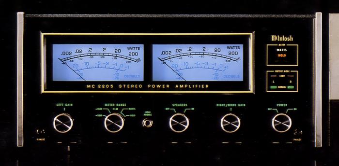
Equipped with an independent power meter for left and right channels.
The meter has Watts and Decibels scales. If you change the meter range to 0 dB or -20dB, the meter is displayed on the decibels scale.
.JPG)
.JPG)
Model Rating
| Type | Stereo power amplifier | ||||
| Output |
|
||||
| Output load impedance | Stereo : 1 Ω, 2 Ω, 4 Ω, 8 Ω Mono : 0.5 Ω, 1 Ω, 2 Ω, 4 Ω |
||||
| Rated output band | 20 Hz to 20 kHz | ||||
| Total harmonic distortion factor (when both channels are driven) | 0.1% or Less (Output 0.25W ~ 200W, 20 hz ~ 20 khz) | ||||
| Cross modulation distortion factor | 0.1% or Less (at Rated Output) | ||||
| Frequency response (at 1W output) | 20 Hz ~ 20 kHz + 0 -0.25 dB 10 Hz ~ 100 kHz + 0 -3.0 dB |
||||
| Signal-to-noise ratio | 95 dB or more (at rated output) | ||||
| Output voltage | 25V | ||||
| Damping factor |
|
||||
| Input Sensitivity / Impedance | 0.75 V, 2.5V/100k Ω | ||||
| Semiconductor used | Silicon transistor : 49 units Silicon Diode : 45 pcs IC : 8 |
||||
| Pwer | 120 V, 50Hz/60Hz | ||||
| Power consumption | 70W (no signal) 550W (at maximum rated output) |
||||
| External dimensions | Front panel : 411.2 mm wide x 181 mm high Body : Width 381x Height 166.7x Depth 368.3 mm |
||||
| Weight | 38.6kg 44.0 kg (when packed) |