McIntosh MC2125
¥ 566,000 (around 1980)
Commentary
A stereo power amplifier equipped with a power guard system unique to Macintosh.
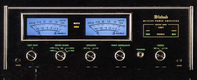
The Power Guard System is a circuit realized by a waveform comparison circuit originally designed by the Macintosh. It electrically compares the output waveform with the input waveform. When the waveform difference reaches 0.5%, the Limit lamp lights and the Normal lamp goes off. When the waveform difference reaches 1%, the Power Guard circuit operates to prevent clipping of the amplifier, to prevent distortion from reproducing from the speaker, and to protect the speaker.
The input and output waveforms are compared by an IC differential amplifier, and the waveform difference due to distortion of the output waveform is converted into a voltage. This voltage is amplified approximately 100 times, passed through a full-wave rectifier circuit, and supplied to a Schmidt trigger circuit. This voltage activates the power guard circuit and activates the power guard circuit when the voltage rises above the level that turns on the Limit lamp.
The Limit lamp is designed to light up when the amplifier is overloaded, and is lit for a visible period of time, even when the overload condition is very short. In this case, the meter will display 200W squid.
When using a power guard circuit, the power guard switch on the rear panel must be set to Normal. Even when this switch is in the out position, only the Limit lamp is active.
The output signal of the amplifier is fed through an output transformer, which is designed to match the output terminal of any impedance and provides the maximum output for all frequency signals regardless of which output terminal is used.
The transformer also protects the speakers in the event of an amplifier failure. For example, if a DC component is mixed into the output, the transformer eliminates the component and prevents damage to the speakers.
To prevent overloading of the output transistor, the output signal is always monitored by a monitor circuit, which becomes high impedance when the output level exceeds the rated value. When the output reaches its maximum value, the monitor circuit limits the signal supplied to the output transistor to prevent damage to the output transistor.
It is equipped with two output indicator meters. The meter is graduated in watts and decibels. When the meter range knob is set to 0 dB or -20dB, the peak value of the signal is displayed on the decibel scale. When the knob is set to WATTS, the output is displayed on the watt scale.
The scale shows the output of the sine wave signal as an average value, and the peak of the signal is also judged from this scale. For example, the scale of 120W indicates that the instantaneous peak of the signal is 240W.
The peak hold function allows the meter to be fixed at the maximum value for reading.
The input side of the power amplifier section uses a monolithic transistor differential amplifier with low noise to eliminate distortion. The input signal and feedback signal are supplied to the differential amplifier. The next stage circuit is a voltage amplifier circuit that operates at class A. The driver circuit and the output circuit use the complimentary service method and operate close to class A to reduce crossover distortion. The circuit is designed to be biased appropriately against temperature changes at all times.
The power transistor is class AB operation and the bias current is kept safe by thermistors. The output circuit is a single-ended para-push type and consists of six highly reliable complimentary service power transistors. This circuit is balanced emitter-follower coupling and is stable with less distortion. In addition, the unique output-bias circuit provides class B operation with no crossover distortion.
.JPG)
.JPG)
Model Rating
| Type | Stereo power amplifier | ||||
| Rated output |
|
||||
| Output load impedance | Stereo : 2 Ω, 4 Ω, 8 Ω, 16 Ω Mono : 1 Ω, 2 Ω, 4 Ω, 8 Ω |
||||
| Rated output band | 20 Hz to 20 kHz | ||||
| Total harmonic distortion factor | 0.1% or Less (Output 0.25W ~ 120W, 20 Hz ~ 20 kHz, Both Channel Operation) | ||||
| Cross modulation distortion factor | 0.1% or Less (at Rated Output) | ||||
| Frequency response (at 1W output) | 20 Hz ~ 20 kHz + 0 -0.25 dB 10 Hz ~ 100 kHz + 0 -3.0 dB |
||||
| Signal-to-noise ratio | 95 dB or more (at rated output) | ||||
| Output voltage | 25V | ||||
| Damping factor | Stereo : 16 (2 Ω), 50 (4 Ω), 20 (8 Ω), 14 (16 Ω) Mono : 16 (1 Ω), 50 (2 Ω), 20 (4 Ω), 14 (8 Ω) |
||||
| Input Sensitivity / Impedance | 0.75 V, 2.5 V (Switching Type) / 100k Ω | ||||
| Semiconductor used | Silicon transistor : 45 pieces IC : 8 Silicon Diode : 45 pcs |
||||
| Power supply voltage | 120 VAC, 50Hz/60Hz | ||||
| Power consumption | 50W (no signal) 460W (at maximum rated output) |
||||
| External dimensions | Body : Width 381x Height 127x Depth 330.2 mm Front Panel : 406.4 mm W x 138.1 mm H |
||||
| Weight | 29.5 kg (net) 35.0 kg (when packed) |