LUXMAN M-4000
¥ 350,000 (released in August 1975)
Commentary
This is a stereo power amplifier equivalent to the small output version of the M-6000.
The main amplifier section consists of a double-stage differential-amplifier circuit, all-stage direct connection pure complimentary service OCL system, and triple push-pull output-circuit.
The output stage employs a triple push-pull configuration using six power transistors per channel with high fT (high-cut-off frequency) and gain as much as possible. Using the excellent linearity of the hfe-Ic characteristic of each transistor, stable operation at a low distortion rate from high output to low output is achieved.
An emitter-follower circuit is installed between the pre-drive stage of class A operation and the output stage of class B operation. This circuit prevents distortion characteristics from deteriorating due to impedance changes caused by the speaker load reaching the pre-drive stage, and improves the load condition in the high-frequency range of the pre-drive stage. In addition to providing constant current drive at important points, a transistor with high fT and low Cob (collector output capacity) is adopted. This enables stable low-distortion drive over the entire band with only light phase correction.
The power supply consists of four large-capacity capacitors (15,000 μ F) combined with two high-efficiency and low-leakage toroidal transformers. In addition, the output stage of class B operation is divided into left and right channels, and the power supply to the pre-drive stage of class A operation is supplied with a constant voltage. This realizes an ideal power supply system in which both channels operate simultaneously and one channel operate at the same output.
It also has a circuit to control the rush current when the power switch is turned on.
As protection circuits, a DC drift detection circuit for speaker protection, an abnormal current detection circuit for amplifier protection, a heat sink abnormal temperature detection circuit, and a fuse blown detection circuit for power transistor monitoring are mounted.
The input circuit uses a 1-dB step precision level detent volume similar to a high-grade attenuator for level setting.
It is also designed to provide electrical isolation between the control amplifier and the main amplifier circuit by providing a constant-current driven emitter-follower stage so that both operate in the best condition.
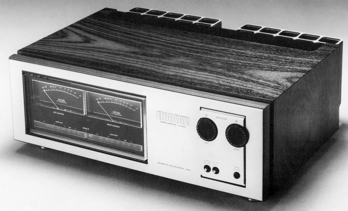
It is equipped with a large VU meter with average level indication and LED peak indicator with peak value indication.
It is also equipped with an output display sensitivity switching function of 0 db ~ -10dB and an output display OFF switch.
Model Rating
| Type | Stereo power amplifier |
| Continuous effective output | 180W + 180W (8 Ω, Both Channel Operation / Single Channel Operation, 20 Hz to 20 kHz) 270W + 270W (4 Ω, Both Channel Operation / Single Channel Operation, 20 Hz to 20 kHz) |
| Total harmonic distortion factor | 0.02% or Less (8 Ω, 180W, 20 Hz to 20 kHz) |
| Cross modulation distortion factor | 0.02% or Less (8 Ω, 180W, 60 hz : 7 khz = 4 : 1) |
| Frequency characteristic | 3 Hz to 100 kHz - within 1 dB |
| Output bandwidth | 5 Hz to 30 kHz -1dB (0.02%) |
| Input Sensitivity / Impedance | 1.0V/50k Ω |
| Signal-to-noise ratio | 106 dB or more |
| Residual noise | 0.2 mV or less |
| Damping factor | 100 (8 Ω) |
| Attachment | VU meter & peak indicator for output display Output display sensitivity selector switch Output display ON-OFF switch Left / Right Channel Independent Input Level Set (1 db step, 22 points) |
| Protection circuit | Speaker protection circuit by detecting DC drift of the speaker terminal Amplifier protection circuit by eddy current detection Amplifier protection circuit by heat sink temperature detection Amplifier protection circuit by detecting fuse blown for power transistor |
| Semiconductor used | Transistor : 120 units Zener diode : 5 pcs Varistor : 6 pieces Diode : 70 pcs LED : 15 |
| Power supply voltage | 100 VAC, 50Hz/60Hz |
| Power consumption | 120 VA (No Signal) 750 VA (8 Ω, both channel operation, at rated output) |
| External dimensions | Width 485x Height 175x Depth 390 mm |
| Weight | 30kg |