LUXMAN M-2000
¥ 225,000 (released in December 1975)
Commentary
This stereo power amplifier was announced as a sister unit of the M-4000.
The main amplifier consists of an all-stage direct connection pure complimentary service OCL system and parallel push-pull connection using a 2-stage differential-amplifier circuit.
The output stage employs a parallel push-pull configuration using four high-output power transistors. The linearity of the hfe-Ic Ic characteristics of each transistor, stable operation at a low distortion rate from high output to low output is enabled.
In addition, an emitter follower is provided between the pre-drive stage of class A operation and the output stage of class B operation to prevent the distortion factor characteristics from deteriorating due to the impedance fluctuation caused by the speaker load reaching the pre-drive stage, and to improve the load condition in the high-frequency range of the pre-drive stage. In addition, constant current circuits are provided at important points, and transistors with high fT (high-frequency cutoff frequency) and low Cob (collector output capacity) are used in the pre-drive stage. This enables stable low-distortion factor drive over the entire band by only applying light phase correction.
The power supply consists of a separate power supply circuit for the output stage of the left and right channels and a combination of two electrolytic capacitors (10,000 μ Fx2) for ± 2 power supply. In addition, the power supply for the pre-driver stage is fully constant voltage. This prevents distortion due to interference between the left and right channels, and eliminates the influence of fluctuations in AC power supply voltage and power supply current.
The protection circuit is equipped with a DC drift detection circuit to isolate and protect the speaker system when a DC voltage of ± 3 v or more is generated at the speaker terminals.
In addition, it is equipped with an abnormal current detection circuit that suppresses the current electronically and keeps it in the ASO region when an excessive current that destroys the power transistor flows, and cuts off the current with a fuse only when the current continues for more than the set suppression time.
The input circuit uses a 1-dB step precision detent volume for each left and right channel, which is the same type as a high-quality attenuator, for level setting.
The emitter-follower circuit is placed in front of the main amplifier circuit so that both the control amplifier and the main amplifier circuit operate in the best condition.
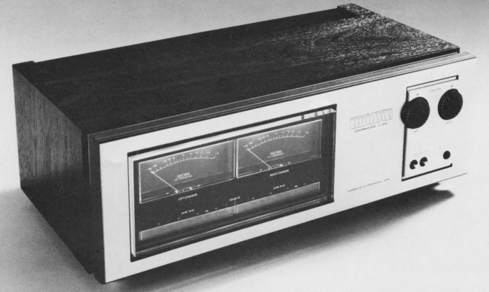
It is equipped with a large VU meter with average level display and an LED peak indicator that displays instantaneous peak values.
In addition, it is equipped with output display sensitivity switching of 0 dB ~ -10dB and output display OFF switch.
Model Rating
| Type | Stereo power amplifier |
| Continuous effective output | 120W + 120W (8 Ω, both channel operation / single channel operation, 20 Hz to 20 kHz) |
| Total harmonic distortion factor | 0.02% or Less (8 Ω, 120W, 20 Hz to 20 kHz) |
| Cross modulation distortion factor | 0.02% or Less (8 Ω, 120W, 60 hz : 7 khz = 4 : 1) |
| Frequency characteristic | 5 Hz to 100 kHz - within 1 dB |
| Output bandwidth | 5 Hz to 50 kHz -3dB (0.05%) |
| Input Sensitivity / Impedance | 800mV/50k Ω |
| Signal-to-noise ratio | 100 dB or more |
| Residual noise | 0.2 mV or less |
| Damping factor | 100 (8 Ω) |
| Attachment | VU meter & peak indicator for output display Output display sensitivity selector switch Output display ON-OFF switch Left / Right Channel Independent Input Level Set (1 db step, 22 points) |
| Protection circuit | Speaker protection circuit by detecting DC drift of the speaker terminal (With Lamp for Protective Circuit Operation Indication) Amplifier protection circuit by eddy current detection |
| Semiconductor used | Transistor : 102 units Zener diode : 5 pcs Varistor : 8 pcs Diode : 74 units LED : 15 |
| Power supply voltage | 100 VAC, 50Hz/60Hz |
| Power consumption | 55W (No Signal) 450W (8 Ω, both channel operation, at rated output) |
| External dimensions | Width 485x Height 175x Depth 295 mm |
| Weight | 18kg |