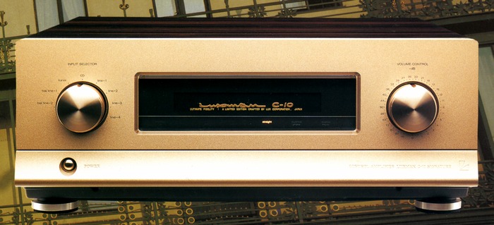
LUXMAN C-10
¥ 1,200,000 (released in October 1996)
Commentary
Control amplifier with Super Ultimate Attenuator.
The volume is equipped with a Super Ultimate Attenuator, which is an attenuator composed of four 58 contacts.
In this attenuator, a fixed volume of 58 points is set by independent resistance voltage divider circuits and switched by ultra-large high-precision rotary contacts. By this, all setting of each volume is always composed of only two resistors (0 dB and one - ∞ position), and the other resistors are completely disconnected. In order to make this into a balanced circuit, it is composed of four circuits. Carefully selected 456 high-precision fixed resistors are mounted discretely on each ultra-large rotary contact. The signal attenuation at the volume section is minimized by this super-ultimate attenuator.
When you control the level of the Super Ultimate Attenuator, the waveform of the music may sound click-like in synchronization with the operation. This is due to the principle of the attenuator that the waveform becomes a step-up or step-down waveform.
The C-10 uses a balanced CSSC (Complementary Single Stagger Circuit) circuit.
The CSSC circuit is a single-staggered circuit with pure complimentary service configuration connected to all stages. The first stage of the circuit consists of a voltage amplification stage using a transistor / complimentary service circuit. While ordinary circuits require positive phase correction, the second stage of the CSSC has a sufficiently high cut-off frequency and realizes stable operation with minimum correction. As a result, a natural sense of freedom and sound field without atrophy can be obtained.
The two stage Darlington complimentary service emitter-follower circuit ensures a sufficiently low output impedance.
The C-10 uses a fully balanced complimentary service single-stagger circuit configuration that combines two CSSC circuits. In addition, the amplifier reference point, which is an absolute condition for the balanced configuration, is obtained by the CSSC circuit that completely eliminates the ground potential difference and clarifies the reference point. This realizes a fully balanced amplifier. By driving two amplifier blocks under the same condition, the potential difference and phase difference in time axis caused by the reference point are resolved.
A buffer amplifier of the complimentary service configuration is inserted at the input to the CSSC circuit.
The first stage of this circuit is a low-noise, high-admittance type silicon junction FET, and the second stage is high-f.TAnd emitter follower with high-Hfe-type transistors to ensure high input impedance while transmitting signals to the CSSC circuit with high-speed characteristics.
A unique OD β circuit is used to unify all bands with natural tones.
In general amplifier circuits, NFB compensation is used to improve electrical characteristics. In particular, in order to ensure stability as an amplifier in the DC range, DC feedback is applied in a separate loop from the normal NFB. In addition, a DC servo amplifier is inserted into the feedback loop to provide powerful control. However, the servo amplifier affects the tone quality in the low-frequency range, resulting in inconsistency between the sound quality in the mid - and low-frequency ranges.
The C-10 uses a CSSC circuit to dramatically improve DC stability. In addition, by refining the bare characteristics of the circuit to a high degree, the DC servo amplifier, which causes harmful effects on sound quality, is eliminated. In the NFB of all bands, the optimal feedback amount is set for each circuit by pouring the know-how of the Lux tradition, and the sound quality is unified by controlling the energy balance of all music bands.
High-inertia power supply is used for the power supply part.
The conventional stabilized power supply is controlled by a large amount of NFB, and by keeping the impedance of the virtual power supply low, the fluctuation of the power supply voltage is apparently reduced. However, there is a time lag between the response of music, which fluctuates rapidly, and the feedback of the response until the control is activated. When observed microscopically, the power supply voltage fluctuated little by little. Moreover, at a point slightly away from the feedback point, the fluctuation was large, causing a remarkable fluctuation in the music signal.
In the high-inertia power supply, power is supplied to the load through a large-capacity capacitor, which is a reservoir of power supply energy, instead of stabilizing the power supply by conventional voltage control using a regulator circuit, etc. In addition, high-quality large-capacity capacitor with excellent instantaneous supply capability developed by LUX's unique know-how to realize this circuit is adopted, and a power supply part that retains constant energy without being affected by fluctuations in current flowing to the load is realized.
In addition, the regulator circuit for charging the capacitor does not reduce the output impedance of the circuit unnecessarily, but uses the minimum necessary NFB control to keep the potential of the capacitor constant. This eliminates the problem of small power fluctuations caused by excessive feedback.
The large-capacity custom capacitor used in the high-inertia power supply meets the conflicting requirements of large-capacity and high-response. It has been developed jointly with capacitor manufacturers for many years to tune the instantaneous charge / discharge capacitor for use in audio equipment. It was originally a capacitor with special specifications. This capacitor meets the conflicting requirements of large-capacity and high-response.
In order to realize a cleaner and more stable power supply, we have adopted a completely independent power supply room system.
By storing power transformers, rectifier diodes, block capacitors, etc. in this power unit, we not only cut off leakage flux, but also isolate the entire power supply room from the main chassis with anti-vibration material against mechanical vibration, shutting out both electromagnetic and mechanical noise components from the power supply.
The C-10 is designed to eliminate interference between circuit blocks, electromagnetic noise from the outside, and high-frequency noise. For example, each circuit block is laid out in a completely shielded structure, while shielding zones of high-frequency electromagnetic absorbers are provided at important points.
The internal construction is based on a 5-point grounding mass FRP base bottom structure with excellent vibration absorption mode and extremely high stability, and each part is mounted by thick and hard chassis material.
This blocks the influence of unwanted vibration and resonance and prevents mechanical noise.
The C-10 uses custom parts developed through repeated trial manufacture for power transformer and CR parts.
In addition to the use of small-capacity capacitors and copper-plated Styrofoam capacitors with copper shields, the enclosed gold-plated contact relay used for switching signal systems is also custom-made with Lux Special Specifications. This relay achieves more complete surface contact by polishing the contact points.
The NF type tone control of the rack system is adopted for the tone control, and it can be adjusted to suppress the undulation and unnatural habit of the frequency at the flat point.
This tone control circuit tone control circuit is bypassed by a line straight switch so that a flat frequency characteristic can be obtained directly.
It has two coaxial Route 6 and balanced inputs and two coaxial and balanced outputs. You can select either coaxial or balanced for bi-amp drive.
There are two tape input / output systems, and the balance / unbalance conversion amplifier for recording output uses a newly developed hybrid IC chip to achieve high-precision conversion.
The balanced input / output terminals are made of highly reliable and durable materials such as metal type XLR terminals.
Uses an aluminum machined front panel.
Inside the sealing pocket, an inverted switch for switching between hot and cold at the balanced input, a reverse mode switch for exchanging L/R for output, and a line straight switch are installed.
.jpg)
.jpg)
.jpg)
.jpg)
.jpg)
.jpg)
.jpg)
.jpg)
.jpg)
.jpg)
.jpg)
.jpg)
Model Rating
| Type | Control amplifier |
| Input Sensitivity / Impedance | Tuner, CD, Line1-4 : 150mV/50k Ω Balance Line1, 2 : 150mV/100k Ω |
| Output Level / Impedance | Coaxial : rated 1V/300 Ω, maximum 7.5 V Balance : rated 1V/600 Ω, maximum 7.5 V |
| Total harmonic distortion factor | 0.005% or less (rated) |
| Frequency characteristic | 20 Hz ~ 20 kHz + 0 -0.1 dB |
| Signal-to-noise ratio | 110 dB or more |
| Tone control | Bass : ± 8 dB max, ± 6 dB (100 Hz), turnover 300 Hz Treble : ± 8 dB max, ± 6 dB (10 kHz), turnover 3 kHz |
| Accessory function | Tape dubbing : 2 systems (1 → 2, 2 → 1) REC OFF Straight Switch Output mode selector switch Remote (Power) output Line phase sensor Output phase selector switch |
| Power supply voltage | 100 VAC, 50Hz/60Hz |
| Power consumption | 38W (regulated by Electrical Appliance and Material Control Law) |
| External dimensions | Width 467x Height 187x Depth 475 mm |
| Weight | 23.0kg |
.jpg)