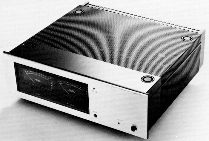
LUXMAN 5M21
¥ 240,000 (released in February 1977)
Commentary
Stereo power amplifier of laboratory reference series.
A parallel push-pull configuration is adopted in which four large output power transistors are inserted in the output stage.
In this series, the concept of Realtime Processed is given, and not only spatial waveform but also temporal problem (transient distortion) is pursued at the same time.
The 5M21 employs a DC amplifier configuration in the circuit to eliminate phase distortion in the low range and transient distortion in the high range.
To solve the problem of DC-drift caused by changes in temperature and other external conditions, we have developed and installed DML-01, a unique DML-IC (Dual Monolithical Linear-Integrated Circuit).
In the DML-IC, a newly developed differential amplifier circuit using FET, a supplementary cascode circuit, a current mirror circuit and a constant current circuit are enclosed in blocks for each circuit to reduce the influence of external temperature changes.
This DML-IC realizes a DC drift level superior to that of an AC amplifier.
In order to eliminate notching distortion in the high-frequency range, transistors with high switching speed are used in the power stage and drive stage, and elements with high switching speed such as Schottky diodes and transistors are connected cascode in the driver stage. As a result, the switching time of the transistor is improved more than that of the transistor itself. In addition to the AB class operation in which idling current is supplied to the extent that the maximum output is not reduced, Cob (collector output capacity) is reduced as much as possible, and the circuit is stable even if the phase correction is small.
By these measures, the notching distortion level superior to that of A-class operation has been realized.
An emitter-follower circuit with constant current drive is provided to improve the high-frequency load condition of the predrive circuit to take advantage of the differential amplifier circuit. An emitter-follower circuit with constant current drive is also provided to insulate the predrive circuit for A-class operation from the influence of the pure complimentary service outputting circuit for A-class operation.
In addition, cascode circuits and constant current circuits are installed at important points to improve basic performance and to perfect DC drift countermeasures.
The power supply consists of two large toroidal power transformers with high thermal efficiency and minimal leakage minimal leakage, and four custom-made ultra-low impedance large-capacity electrolytic capacitors. The power supply consists of a left and right channel-independent system.
It is equipped with a large VU meter with independent left and right channels that can display average output in decibels.
This VU meter can change the meter range from 0 dB to -10dB.
Equipped with a DC offset sensor, it can check DC component is input from the outside.
It also has an input capacitor IN/OUT switching function so that when a DC component appears at the output terminal, it can be cut off by the input.
It has an independent input attenuator for the left and right channels.
Equipped with 3 types of protection circuits.
The DC drift detection circuit protects the speaker when a DC current of ± 3 v or more appears at the output terminal.
In addition, the heat sink abnormal high temperature detection circuit protects the amplifier when the heat sink becomes abnormally high temperature of 90 ℃ or more.
In the eddy current prevention circuit, the output terminal is short-circuited to protect the amplifier when an eddy current flows into the power transistor.
It uses carefully selected parts such as metal film type semi-fixed VR with excellent temperature characteristics and low noise, resistance, and silbird mica type capacitor with excellent temperature characteristics and high frequency characteristics.
It employs a horizontally stacked heat sink with high heat radiation efficiency and a speaker terminal that minimizes contact resistance.
In the Laboratory Reference Series, in which legs are attached to the lower part and metal brackets are attached to the upper part, and these are supported by metal supports, so that when the product is stacked, an excessive load is not applied to the product lying below.
In addition, the legs and brackets fit together perfectly so that they do not slip or fall over.
As an optional part sold separately, there was a standard rack mounting bracket of EIA standard.
.jpg)
.jpg)
.jpg)
Model Rating
| Type | Stereo power amplifier |
| Continuous effective output | 100W + 100W (8 Ω, simultaneous operation of both channels, 20 Hz to 20 kHz) |
| Total harmonic distortion factor | 0.005% or Less (8 Ω, 100W, 20 Hz to 20 kHz) |
| Cross modulation distortion factor | 0.005% or Less (8 Ω, 100W, 60 hz : 7 khz = 4 : 1) |
| Frequency characteristic | DC ~ 100 kHz -1dB |
| Output bandwidth | 5 Hz to 100 kHz -3dB (8 Ω, 0.1%) |
| Input Sensitivity / Impedance | 890mV/50k Ω |
| Signal-to-noise ratio | 120 dB or more (IHF-A curve correction, input short circuit) |
| Residual noise | 0.1 mV or Less (Input Short) |
| Crosstalk | -100dB or less (100 Hz) -70dB or less (20 Hz to 20 kHz) |
| Damping factor | 80 or More (8 Ω, 1 kHz) |
| Protection circuit | DC offset sensor Speaker protection circuit with DC drift detection Amplifier protection circuit by detecting heat sink abnormal high temperature Eddy current prevention circuit |
| Attachment | Independent left / right channel VU meter Meter range switching (0 dB → 10 dB) Input capacitor IN-OUT switching Independent left and right channel attenuator Terminal for peak indicator connection |
| AC outlet | Unswitched : 1 line, 500W |
| Power consumption | 450W (8 Ω, both channels operate simultaneously, at rated output) |
| External dimensions | Width 442x Height 146x Depth 400 mm |
| Weight | 19.0kg |
.jpg)
.jpg)