.jpg)
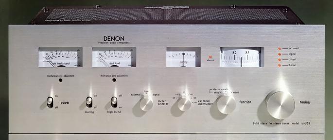
DENON TU-355
¥ 75,000 (around 1975)
Commentary
FM stereo tuner using drum type tuning system.
A drum type tuning system is used for the dial part.
In this system, a 12 cm diameter drum is used for the dial part, and the scale is lengthened while the panel area is reduced. The total travel length of the scale (75 ~ 91 MHz) is 28.3 cm, and it is easy to see that one scale is equal spacing of 200 kHz together with the frequency proportional type varicon.
Since high-precision stainless steel shaft and alloy bearing are used for the dial rotation mechanism, even the frequently used tuning knob maintains the initial smoothness for a long time.
The tuning instruction is a 2-meter type consisting of a signal meter and a center type tuning meter.
The large meter at the left end is also used as a signal meter and can read the input voltage of the antenna terminal.
The left and right level meters can also be used as independent measuring instruments.
With a high input impedance of 200k Ω, it is possible to measure the steady state audio signal voltage from approximately -30dB (24.5 mV) to + 33 dB (34.6 V) by switching the front external Att.
It can also be used as an amplifier output meter by combining it with an amplifier that does not have a level meter.
In the front-end section, the input signal is first passed through a single tuning circuit of a series of varicon, and then the high-frequency amplification of the dual-gate MOS-FET is performed immediately to maintain high S/N against weak radio waves.
After that, it is mixed and amplified with local oscillation frequency by a dual-gate MOS-FET through a triple tune circuit of three varicon series, and the configuration is designed so that it does not distort even strong radio wave and does not cause blocking phenomenon with appropriate gain setting.
A modified clap-type oscillation circuit is used for the local oscillation circuit. This circuit has many advantages such as that the transistor is less affected by voltage fluctuation and temperature change due to the grounded collector type, and the output has less harmonics.
In addition, a temperature compensation capacitor and an oscillation coil with resistance to temperature and humidity are adopted. Moreover, the oscillation output is injected into the second gate of the dual gate FET for mixing through one stage of buffer amplifier, so the oscillation frequency is extremely stable. This eliminates the problematic AFC circuit.
The IF section consists of two circuits. It consists of an original amplifier circuit and a sub amplifier circuit for the control system such as signal meter, multi-pass vertical output terminal and muting circuit. This configuration reduces the occurrence of new harmonics, phase modulation and cross modulation interference in the main IF section.
The main through differential amplification by transistors with a wide dynamic range, the main amplifier circuit forms multistage amplification with good linearity mainly by IC-2 pairs directly connected to three stages of differential amplification. Four pairs of ceramic 2-element type filters with high selectivity and flat phase characteristics with an emphasis on sound quality are used as coupling and selection elements between them. Finally, a ratio detection circuit for wide band with low output impedance is adopted for FM detection.
A PLL circuit is used in the MPX section.
Both the left and right channels of the low-frequency amplifier are designed as two stage direct-coupled amplifier circuits.
In addition, unnecessary leakage such as pilot signal and subcarrier is cut off with a low-pass filter of LC3-stage configuration.
Equipped with muting switch and high blend switch.
The Function Selector has a Stereo only position in addition to Mono and Auto positions.
This is a convenient function to select only stereo programs from the broadcast.
There was a wood cabinet as an optional item sold separately.
.jpg)
.jpg)
.jpg)
Model Rating
| Type | FM tuner |
| Tuner Section | |
| Circuit system | Frontgate MOS FET, RF1 stage, front end of 5 series varicon IF stage using 4 2-element phase flat filter |
| Receiving frequency range | 76 MHz to 90 MHz |
| Intermediate frequency | 10.7MHz |
| Practical sensitivity (IHF) | 1.7 μ V |
| S/N 50 dB sensitivity | 33 μ V |
| Effective selectivity (2-signal method)) | 85dB(IHF) |
| Image interference ratio | 120dB(83MHz) |
| IF interference ratio | 110dB(83MHz) |
| Capture Ratio (IHF) | 1.0dB |
| Spurious response | 110dB(83MHz) |
| AM suppression ratio | 60dB(IHF) |
| <Audio section> | |
| Circuit system | Adoption of phase-locked loop type stereo demodulation circuit |
| 19 kHz & 38 kHz suppression ratio | 75 dB or more |
| Frequency characteristic | 20 Hz ~ 15 kHz + 0.2 -0.5 dB (with 19 kHz Filter) |
| Signal-to-noise ratio | mono:80dB stereo:75dB |
| Total harmonic distortion factor | Stereo : 0.15% at 1 kHz, 90% modulation Mono : 0.1% at 1 kHz, 100% modulation |
| Stereo separation | 45dB(1kHz) 40 dB (100 Hz to 10 kHz) |
| Output voltage (at 100% modulation) | Fixed : 1 Vrms Variable : 0 V ~ 1.5 Vrms |
| Output impedance | Fixed : 4.7k Ω Variable : 1k Ω |
| Level Meter Section | |
| External signal measuring range | -20, -10, 0, + 10, + 20, + 30 dB (0 dB, 0.775 Vrms) |
| Input impedance | 150k Ω or more 200k Ω or more (listed in separate catalog) |
| Indication error | Within ± 0.2 dB (each range, 1 kHz, near VU scale 0) |
| Frequency characteristic | 20 Hz to 15 kHz ± 0.5 dB |
| <General> | |
| Connection terminal | Antenna terminal : 75 Ω F-type connector, 300 Ω, 75 Ω, screw type Multipath detection terminal, detection output terminal (output for 4 ch & SCA), audio output terminal (fixed / variable) Level meter external terminal and same path terminal |
| Pwer | 100 VAC, 50Hz/60Hz |
| AC Socket | Unswitched 250 Wmax, single line |
| Power consumption | 16W |
| External dimensions | Width 396x Height 147x Depth 281 mm |
| Weight | 6.8kg |
| Sold Separately | Wood Cabinet ACA-5 (¥ 5,000) |
.jpg)