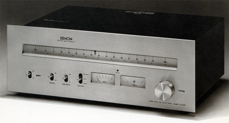
DENON TU-335
¥ 54,800 (around 1976)
Commentary
FM stereo tuner with TU 500 and TU 355 technology.
The dial scale is 200 kHz equally spaced (3.4 mm) to express the usability and the accuracy of the tuner.
In addition, the dial mechanism uses a flywheel with a large moment of inertia, a high-precision stainless steel shaft, and alloy bearings to maintain smooth running.
The signal meter circuit employs a multi-stage amplification stage and detection system. This makes it possible to swing the signal meter in proportion to the strength of the input radio wave from the strong electric field to the weak electric field. The strength of the input radio wave at the time of broadcast reception can be measured, and the state of the radio wave can be monitored as with the multi-path terminal.
It is also equipped with a tuning meter that provides the best tuning with the least distortion.
A boardless package type is adopted for the front end part to improve basic performance such as sensitivity, S/N, stability, and temperature characteristics.
It features a high-precision frequency linear 5-row varicon, low-noise dual-gate MOS-FET, and a triple-tune circuit with flat phase characteristics and excellent selection characteristics.
The local oscillation circuit employs a clap-type oscillation circuit that is resistant to voltage and temperature fluctuations. In addition, the oscillation frequency fluctuation is minimized by using a temperature compensation capacitor and an oscillation coil that is resistant to temperature and humidity, thereby eliminating the need for an AFC circuit.
The IF section consists of two circuits. In addition to the IF amplifier section, it is a sub amplifier (consisting of four transistors) for control systems such as signal meters, multi-pass vertical output circuits and muting circuits.
The IF main amplifier circuit uses differential amplification by a discrete transistor with good S/N and two differential amplification 3-stage direct-coupled ICs with ideal limiting (amplitude limiting) function. By using four 2-element ceramic filters as coupling selection elements between them, low distortion and high separation are obtained.
A ratio detection circuit is used for FM detection.
The MPX circuit uses an IC with a PLL circuit configuration.
We have also studied the effect of the distorted waveform on sound quality, and particularly aimed at improving sound quality by minimizing nonlinear crosstalk.
In order to completely remove pilot signal (19 kHz) and subcarrier (38 kHz) leaked from the MPX circuit, an independent LC3-stage low-pass filter is used.
As a result, the frequency characteristics are kept within -1.5 dB even at the maximum transmission frequency of 15 kHz, and carrier leakage is suppressed to below the noise level (-75dB or less).
The audio circuit consists of a two stage direct-coupled amplifier and an emitter-follower buffer stage. The two outputs are low-output impedance, so that there is no degradation in characteristics even when the input impedance of the tape deck or amplifier is low or when two output terminals are used simultaneously.
Multi-path terminal is mounted.
This terminal is used to detect unwanted reflected waves. It can be used for optimum antenna installation such as selection of appropriate antenna, direction and height.
The antenna input terminal is equipped with a 75 Ω F-type connector exclusively for coaxial cable to minimize transmission loss and receive weak radio waves.
Built-in 440 Hz test signal oscillator.
The test signal level is 1/2 (-6dB) of 100% modulation of FM broadcasting, 0.5 Vrms at the fixed output terminal and 0.75 Vrms at the variable output terminal when the volume is maximum. This output corresponds to 50% modulation of broadcasting and is used as a reference to adjust the level meter when recording on a tape deck.
This test signal can also be used for balance check and phase check.
Equipped with a muting switch, deep inter-station noise can be eliminated when channel selection.
Equipped with a high-blend switch that cancels out noise without destroying frequency characteristics.
There was a wood cabinet as an optional item sold separately.
.jpg)
.jpg)
.jpg)
.jpg)
Model Rating
| Type | FM tuner |
| Tuner Section | |
| Circuit system | Front end of RF1-stage 5-series varicon using dual gate MOS-FET IF stage using 4 2-element phase flat filter |
| Receiving frequency range | 76 MHz to 90 MHz |
| Practical sensitivity | 1.7 μ V (IHF standard) 3.5 μ V (S/N50dB sensitivity, monaural) |
| Effective selectivity (two signal method) | 85 dB (IHF standard) |
| Image interference ratio | 115dB(83MHz) |
| IF interference ratio | 110dB(83MHz) |
| Spurious response | 115dB(83MHz) |
| AM suppression ratio | 60 dB (IHF standard) |
| Capture Ratio (IHF) | 1.0dB |
| 19 kHz & 38 kHz suppression ratio | 75 dB or more |
| Frequency characteristic | 20 Hz ~ 15 kHz + 0.2 -1.5 dB (with 19 kHz Filter) |
| Signal-to-noise ratio | mono:80dB stereo:75dB |
| Total harmonic distortion factor | Stereo : 0.15% at 1 kHz, 90% modulation Mono : 0.1% at 1 kHz, 100% modulation |
| Separation | 50dB(1kHz) 40 dB (50 Hz to 10 kHz) |
| Output voltage (at 100% modulation) | Fixed : 1 Vrms Variable : 0 V ~ 1.5 Vrms |
| Output impedance | Fixed : 4.7k Ω Variable : 400 Ω |
| Connection terminal | Antenna terminal 75 Ω F-type connector 300 Ω, 75 Ω, Screw Type Multipath detection terminal Detection output terminal (output for 4 ch & SCA) Audio output jacks (fixed, variable) |
| Level Signal Oscillator | |
| Oscillation frequency | 440 Hz sine wave |
| Output Voltage (50% modulation) | Fixed : 0.5 Vrms Variable : 0 to 0.75 Vrms |
| <General> | |
| Pwer | 100 VAC, 50Hz/60Hz |
| Power consumption | 17W |
| External dimensions | Width 396x Height 147x Depth 281 mm |
| Weight | 6.5kg |
| Attachment | Connection code x1 Piece 75 Ω, 3C2V F-Type Stopper x1 |
| Sold Separately | Wood Cabinet ACA-5 (¥ 5,000) |
.jpg)