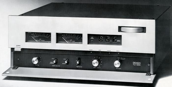
DENON TU-1000
¥ 158,000 (released in 1977)
Commentary
FM stereo tuner using digital tuning method.
The front-end section uses a newly developed frequency linear type 7-row variable capacitor. High selectivity characteristics and interference rejection capability are achieved by 2-stage high-frequency (RF) amplification and triple-double tune configuration (coupled by 3-stage double-tuned circuit).
In addition, to achieve both high S/N and control sensitivity of Quartz Lock APC (Automatic Phase Control), a specially selected low-noise dual-gate MOS-type FET is used, taking advantage of the multiple varicon front-end.
The local oscillator has the function of continuously changing the oscillation frequency to catch a broadcasting station placed at 100 kHz intervals. The TU-1000 employs the quartz-lock-APC method, which enables accurate reception by controlling the local oscillator frequency by an integer multiple of 100 kHz obtained by dividing the frequency from a 10 MHz crystal oscillator.
Equipped with a digital tuning method and digital display mechanism.
The TU-1000 is equipped with a 5-digit digital counter circuit. The upper three digits of the reception frequency are displayed numerically, and the lower two digits are used for digital tuning.
For example, when receiving a 82.5 MHz broadcast station, the LED indicating "Just Tuned" will light when the digital counter detects 82.495 MHz to 82.505 MHz. As a result, the difference between the tuning accuracy and the received frequency is kept within ± 5 kHz (within ± 1/16,500). This enables high-precision tuning that cannot be achieved with conventional analog tuning methods.
When you release the set, the Lock LED lights up to keep the station accurately captured.
In order to achieve both faithful signal transmission and interference rejection capability, the IF amplifier is separated into two systems, Wide and Narrow.
In the WideBand, a specially designed LC linear phase filter is used to flatten the phase characteristics, thereby realizing a low distortion factor. In addition, the shift between the main signal part (L + R) and the sub signal part (L-R) of the composite (detection output) signal is improved to improve separation characteristics.
In addition, the Narrow Band uses a newly developed linear-phase ceramic filter (composed of five filters) to achieve excellent selectivity.
In order to realize the high S/N, which is the development theme of the TU-1000, we have analyzed the relationship between the differential gain and differential phase characteristics and the amount of distortion using a ratio detector that is effective in S/N, and have developed a new constant-impedance coupling type ratio detector. With this circuit, the linear region of the S-shaped curve showing the detection characteristics can be expanded by more than 1.5 times, and harmonic distortion and intermodulation distortion are greatly improved.
In addition, in order to reduce the noise generated by the ratio detector, a silicon-junction diode, which is also used in the TU-850, is used in the detector to achieve high S/N.
The MPX circuit is a Twain MPX circuit with two sets of a PLL circuit for pilot extraction and a switching demodulation circuit.
In this circuit, the fluctuation component due to the false pilot signal appearing at the output end of each low-pass filter of the two pilot extraction circuits is canceled to only the DC component. Therefore, the demodulation switching signal does not contain any unnecessary components, and the L/R signal taken out by the switching circuit does not contain any unnecessary components. Thus, clear sound quality can be obtained. As a result, the intermodulation distortion rate is improved by more than 10 dB to 20 dB compared with the conventional model.
In addition, the left and right signals obtained from the two sets of demodulation circuits are added to each other, so the SN ratio is improved by 3 dB due to the randomness of the noise generated inside the demodulation circuit.
Equipped with a 3-band split separation compensation circuit, it splits into three frequency bands, low, middle and high, and improves the separation characteristics from L to R and from R to L, respectively.
It is equipped with a large peak meter that can check the left and right playback sound levels from -20dB to + 5 dB.
The 0 dB meter corresponds to a modulation output of 100% FM and can be used for air checking. These level meters can also be used to check the electric field strength (signal meter) or as a multipath meter to detect the presence of multipath.
A reliable Hewlett-Packard LED is used for the frequency display and guide lamp.
Equipped with a level variable muting function.
Equipped with a 2-stage switching type high blend switch.
.JPG)
Model Rating
| Type | FM stereo tuner | |||
| FM Tuner Section | ||||
| Receiving frequency | 76 MHz to 90 MHz | |||
| Intermediate frequency | 10.7MHz | |||
| Antenna terminal | 75 Ω (F-type Connector Type, PAL Type, Terminal Type, 1 System Each) | |||
| Practical sensitivity | 1 μ V/11.2 dBf | |||
| S/N50dB sensitivity | Mono : 1.5 μ V/14.8 dBf Stereo : 16.5 μ V/35.7 dBf (μ V at 75 Ω, 0 dBf at 10-15W (new IHF standard) |
|||
| Image interference ratio | 120dB(83MHz) | |||
| IF interference ratio | 120dB(83MHz) | |||
| Spurious response | 120dB(83MHz) | |||
| AM suppression ratio | 65dB(IHF) | |||
| Effective selectivity | Wide : 36 dB (± 400 kHz) Narrow : 90 dB (± 400 kHz) |
|||
| Capture Ratio (IHF) | wide:0.8dB Narrow:1.5dB |
|||
| Subcarrier suppression ratio | 80dB | |||
| Frequency characteristic | 20 Hz to 15 kHz + 0.2 -0.8 dB | |||
| Signal-to-noise ratio | mono:87dB stereo:84dB |
|||
| Total harmonic distortion factor |
|
|||
| Cross modulation distortion factor |
|
|||
| Stereo separation |
|
|||
| Muting action level | Off, 30 dBf ~ 70 dBf continuously variable | |||
| FM detection output | 350 mv (at 100% modulation) / 10k Ω or more | |||
| Multipath output | Vertical : 150 mV (equivalent to AM30% modulation) / 10k Ω or more Horizontal : 350 mV (corresponding to FM100% modulation) / 10k Ω or more |
|||
| Accessory function | Two large peak level meters Left : Lch output level, multipath vertical level Right : Rch output level and signal level off-2-stage switching high blend switch |
|||
| Output (at 100% modulation) | Fixed : 1.2V/10k Ω or More Variable : 0 ~ 1.5V/10k Ω or More |
|||
| Tuning instruction | Tuned frequency digital display Just Tuned-Locked LED display Signal meter display |
|||
| Peak Meter Characteristics | ||||
| Indication range | -20dB to + 5 db | |||
| Reference level (0 dB) | 100% modulation | |||
| Indication error | -10 to + 5 dB ± 1.5 dB | |||
| Frequency range | 100 Hz to 10 kHz ± 0.2 dB | |||
| Response time | 80 ms (mechanical response) | |||
| Recovery time | 0.1S | |||
| <General> | ||||
| Pwer | 100 VAC, 50Hz/60Hz | |||
| Power consumption | 23W | |||
| External dimensions | Width 410x Height 170x Depth 307 mm (including leg, knob, terminal) | |||
| Weight | Approximately 10 kg | |||
| Attachment | F Type Stopper (for 3C-2V) x1 1 Parallel Pin Cord |
|||