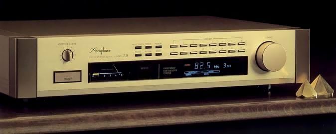
Accuphase T-11
¥ 120,000 (released in April 1990)
Commentary
A synthesizer FM stereo tuner developed in pursuit of the ultimate grade as a tuner for music fans who are concerned with sound quality.
For tuning for channel selection, high-precision tuning is realized by a crystal oscillator, and there is almost no deviation due to time or temperature change, and it is locked at the point of minimum distortion and maximum sensitivity.
Because of electronic tuning, modulation distortion and noise due to external vibration are hardly generated.
Equipped with a 16-station memory tuning function, it can be called up instantly by pressing a button.
In this case, depending on the station, the radio wave is weak and it is necessary to turn on the filter or change the selectivity. However, it is possible to set a function that matches the radio wave condition of the station.
In addition to memory tuning, a pulse tuning manual tuner using a rotary knob is mounted.
This system was developed especially for manual electronic tuning. Pulses are generated by radial slits attached to the shaft of a rotary knob, and the tuning frequency is controlled by counting these pulses.
In the front-end section, the input and amplifier stages are each composed of a double-tuned configuration, and the mixer for frequency conversion is a balloon FET balanced modulator using a differential-transformer to prevent interference due to Dainyu interference.
In addition, it is equipped with a PIN diode attenuator to prevent interference and distortion in any region by operating the transmission tower as a variable attenuator for large excess input near the transmission tower.
The detector stage combines an original DGL detector with a specially selected group-delay flat IF filter to obtain excellent characteristics of stable and undistorted capture ratio.
The DGL detection method focuses on the delay time of the output of a high-speed logic IC. Nineteen of these circuits are connected in series. The phase angle is delayed by 114 degrees so as to minimize distortion and obtain the best SN. The delayed signal and input signal are added to an exclusive OR circuit. The potential between the two signals is selected to open and close the circuit. The degree of compactness of the signal wave generated by modulation is digitally detected and an audio signal is extracted. The linear region of the delay circuit is as wide as ± 2.5 MHz. Moreover, since it is a non-adjustable circuit, stable and excellent linear differential gain characteristics can be obtained.
In addition, two sets of IF filters, Normal and Narrow, are used. When adjacent interference is intense, switching to Narrow enables sharp reception with an emphasis on selectivity.
The stereo demodulation section uses the synchronization pilot signal included in the input signal to lock the internal oscillation circuit with the PLL circuit to obtain an accurate 38 kHz switching signal.
The T-11 uses a combination of a ceramic resonator and a variable positive and negative reactance circuit that can be controlled by the control voltage in the internal oscillation circuit of this PLL, so that accurate switching signals can be obtained in a narrower lock frequency range than before.
This circuit realizes the non-adjustment of the stereo demodulation circuit and maintains the initial characteristics for a long period of time. In addition, the separation does not change due to changes in temperature or line voltage. Moreover, the lock frequency range is much narrower than the conventional one, so that the beat distortion at high frequencies is reduced.
It is equipped with the first balanced output circuit as a tuner to prevent deterioration of sound quality in the transmission system.
It is equipped with a meter that can check the input signal level and multipath with a changeover switch.
When the meter indicator is within the range of the clear mark, multipath indicates that the radio wave of good quality is received with minimum multipath.
It is equipped with a noise filter to reduce the noise of weak stereo stations, a muting switch to remove inter-station noise, a mono switch to force monaural, and an output level control to adjust the volume to other program sources.
A dedicated remote control is included.
The design is unified with the power amplifier P-11, preamp C-11 and CD player DP-11.
.JPG)
.JPG)
.JPG)
.JPG)
.JPG)
.JPG)
.JPG)
.JPG)
Model Rating
| Type | Synthesizer FM tuner | ||||||||||||
| MonAural Characteristics | |||||||||||||
| Receiving frequency | 76.1 mhz to 89.9 mhz | ||||||||||||
| Practical sensitivity | 11dBf(IHF) | ||||||||||||
| S/N 50 dB sensitivity | 17dBf(IHF) | ||||||||||||
| Standing-wave ratio | 1.5 | ||||||||||||
| S/N (80 dBf input, A-correction) | 90dB | ||||||||||||
| Total harmonic distortion factor (80 dBf input ± 75 kHz shift, Normal) |
20Hz:0.02% 1kHz:0.02% 10kHz:0.02% |
||||||||||||
| IM distortion factor | 0.01% (80 dBf input, ± 75 kHz shift) | ||||||||||||
| Frequency characteristic | 10 Hz ~ 16000 Hz + 0 -1.0 dB | ||||||||||||
| Two signal selectivity (IHF) |
|
||||||||||||
| Capture ratio | 1.5dB | ||||||||||||
| RF intermodulation | 80dB | ||||||||||||
| Spurious interference ratio | 120dB | ||||||||||||
| Image ratio | 100dB | ||||||||||||
| AM suppression ratio (65 dBf input) | 80dB | ||||||||||||
| Subcarrier suppression ratio | 70dB | ||||||||||||
| SCA interference ratio | 80dB | ||||||||||||
| Output voltage (± 75 kHz deviation) | 1.0V | ||||||||||||
| Stereo Characteristics | |||||||||||||
| Sensitivity (IHF) | S/N 40dB:29dBf S/N 50dB:37dBf |
||||||||||||
| S/N (80 dBf input, A-correction) | 85dB | ||||||||||||
| Total harmonic distortion factor (80 dBf input ± 75 kHz shift, Normal) |
20Hz:0.04% 1kHz:0.04% 10kHz:0.04% |
||||||||||||
| IM distortion factor | 0.03% (80 dBf input, ± 75 kHz shift) | ||||||||||||
| Frequency characteristic | 10 Hz ~ 16000 Hz + 0 -1.0 dB | ||||||||||||
| Stereo separation factor | 100Hz:50dB 1kHz:50dB 10kHz:40dB |
||||||||||||
| Stereo switching input voltage | 20dBf | ||||||||||||
| <General> | |||||||||||||
| Antenna | 75 Ω unbalanced (with 300 Ω balanced converter) | ||||||||||||
| Tuning system | Quartz synthesizer method 16-station random memory tuning | ||||||||||||
| Detection system | DGL method | ||||||||||||
| Output impedance |
|
||||||||||||
| Meter | Signal strength, multi-path switching | ||||||||||||
| Semiconductor used | Transistor : 15 FET : 5 pcs IC : 32 Diode : 36 units |
||||||||||||
| Pwer | AC100V/117V/220V/240V, 50Hz/60Hz | ||||||||||||
| Power consumption | 15W | ||||||||||||
| External dimensions | Width 445x Height 95 (Including Legs) x Depth 325 mm | ||||||||||||
| Weight | 9.3kg | ||||||||||||
| Attachment : Remote Commander RC-5 | |||||||||||||
| Remote control system | Infrared pulse system | ||||||||||||
| Pwer | DC3V | ||||||||||||
| Dry battery | Use 2 pieces of SUM-3 type (IEC name R6) | ||||||||||||
| Maximum external dimensions | 64 mm wide x 149 mm high x 18 mm deep | ||||||||||||
| Weight | 145g (including dry batteries) | ||||||||||||