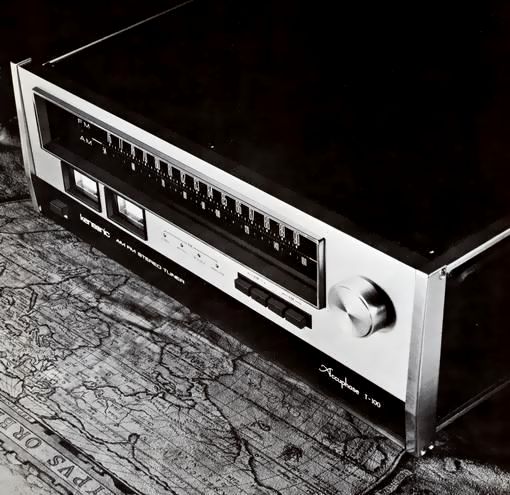
Kensonic Accuphase T-100
¥ 135,000 (Released in September 1973)
Commentary
This is the first AM/FM stereo tuner released by Kensonic (currently AccuPhase) at the same time as the P-300 and C-200 as the Accuphase series.
In order to achieve both the performance as a receiver and the performance as an audio equipment, both of which are contradictory aspects, we have generously introduced the latest high-frequency technology and new materials to challenge the limits of the technology.
At the front end, an antenna enters a high-frequency amplifier circuit, and a mixing circuit mixes it with a local oscillator signal to produce an intermediate frequency of 10.7 MHz.
In addition to the circuit configuration such as the frequency number line 5-series varicon, 2-stage feedback tuning circuit, interstage perfect shield mechanism, local oscillation buffer circuit, etc., dual gate FET is used for the high-frequency circuit and mixing circuit, and spurious interference ratio and image ratio are improved by expanding the input dynamic range.
The intermediate frequency signal generated at the front end enters an intermediate frequency circuit, and adjacent waves are removed, amplified, amplitude limited, and guided to a detection circuit.
In the past, transformers and mechanical filters were used as selection elements for this intermediate frequency circuit. In order to improve the distortion to the level of other high-grade audio amplifiers, we have newly developed a phase linear LC15-stage concentrated filter, which is used in combination with an IC.
In order to demodulate FM intermediate frequency signals into audio signals without distortion, a 1200 kHz wide-band discriminator, which is approximately three times the bandwidth generally used, is used in the detection circuit.
The stereo demodulator, which separates audio signals into left and right stereo signals, uses a phase-locked loop demodulation circuit that automatically synchronizes the phase of the input pilot signal with the subcarrier oscillator without any tuning circuit consisting of coils and capacitors.
In addition to the signal strength meter and the center tuning meter, an independent multi-path meter is installed in the sub panel in order to improve the multi-path (ghost), which causes distortion especially in stereo reception, making it impossible to receive high-quality signals.
By fixing the antenna direction to the direction in which the indication of the meter becomes minimum, stable reception is possible.
The AM tuner section has been designed with low distortion due to the invention of a new detection circuit and research on the appropriate band.
The front end and the intermediate frequency circuit have a luxurious circuit configuration using MOS and J-type FET.
The front sub-panel contains a two stage muting switch, stereo noise filter, AM-FM independent output level control, dial light control, etc. The multi-pass meter lights up automatically when the sub-panel is opened.
.JPG)
Model Rating
| Type | FM/AM Tuner |
| FM MonAural Characteristics | |
| Sensitivity | S/N 40 dB : 2.0 μ V S/N 50 dB : 4.5 μ V IHF sensitivity : 2.0 μ V |
| Saturation point S/N (200 μ V) | 75dB |
| Harmonic distortion factor at saturation point (50 μ V input) | 100 Hz : 0.1% or less 1 kHz : 0.1% or less 10 kHz : 0.1% or less |
| Audio IM distortion rate (70 Hz : 7 kHz = 4 : 1) | 0.2% or Less (Antenna Input 1 mv, 100% Modulation) |
| Frequency characteristic | 20 Hz ~ 15000 Hz + 0 -1dB |
| Two signal selectivity (IHF) | 70dB |
| Capture ratio | 1.5dB |
| Image ratio | 100dB |
| IF interference ratio | 100dB |
| Spurious interference ratio | 100dB |
| AM suppression ratio (1 mV input) | 60dB |
| Frequency stability | ± 30 kHz |
| Frequency accuracy | Within ± 0.1% |
| Output voltage (100% modulation) | 2.0V |
| FM Stereo Characteristics | |
| Sensitivity | S/N 40 dB : 20 μ V S/N 50 dB : 45 μ V |
| Saturation point S/N (2 mV input) | 70dB |
| Harmonic distortion factor at saturation point (500 μ V input) | 100 Hz : not more than 0.2% 1 kHz : 0.2% or less 10 kHz : 0.5% or less |
| Frequency characteristic | 20 Hz ~ 15000 Hz + 0 -1dB |
| Stereo separation factor | 100Hz:35dB 1kHz:45dB 10kHz:30dB |
| Stereo switching input voltage | 5 μ V, 20 μ V (switching in conjunction with muting switch) |
| SCA interference ratio | 60dB |
| Leakage at 19 khz and 38 khz | -70dB |
| <AM Tuner Section> | |
| Sensitivity | Distance : 15 μ V Local : 150 μ V |
| S/N (1 mV input, 1 kHz, 30% modulation) | 50dB |
| Harmonic distortion factor (1 mV input, 1 kHz, 30% modulation) | Not more than 0.5% |
| Selectivity characteristics (± 10 kHz) | 30dB |
| Image ratio | 70dB |
| IF interference ratio | 60dB |
| 10 kHz Whistle Filter | -30dB |
| Output Voltage (30% Modulation) | 0.6V |
| <General> | |
| Output impedance | Fixed output terminal : 200 Ω Variable Output Terminal : 2.5k Ω |
| FM antenna input impedance | Balance : 300 Ω Unbalanced : 75 Ω |
| Meter | 3 pieces Signal strength meter Center tuning Multi-pass meter |
| Variable capacitor used | FM : Frequency Linear Type Precision 5 Series AM : Precision 3 Strand |
| Semiconductor used | FET : 7 Transistor : 45 IC : 9 Diode : 43 pcs |
| Pwer | 100V/117V/220V/240V, 50Hz/60Hz |
| Power consumption | 26W |
| External dimensions | Width 445x Height 152x Depth 355 mm |
| Weight | 14kg |