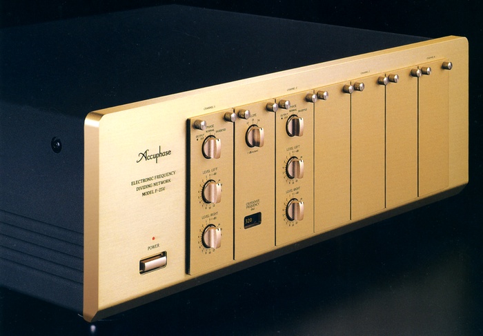
Accuphase F-25V/F-25VM
F-25V
F-25VM: ¥ 390,000 (released in February 2001)
: ¥ 440,000 (released in February 2001)
Commentary
A multi-channel divider that can handle up to 4-way configuration depending on the unit amplifier type.
There are 2 types of variations of this model, F-25V and F-25VM.
The F-25VM is a dedicated model for 2-way (bi-amp) drive of the JBL M9500 and Project K2S 9500 / S 7500. The F-25VM is equipped with a dedicated filter amplifier unit DN-25VM and a dedicated frequency board FB-25M to obtain filter characteristics similar to those of a speaker-LC network. The DN-25VM is fixed at 18dB/oct even when a slope selector switch is installed. 650
It was also possible to convert the F-25V into an F-25VM later.
The F-25V has a filter amplifier and line amplifier as a unit, and has a structure that can be easily attached and detached from the whole panel.
The basic configuration is 2-way specification and comes with 1 filter amplifier and 2 line amplifiers as standard equipment. To increase the number of channels by 3 way or more, optional filter amplifier and line amplifier are added.
One unit of F-25V can handle up to 4 ways, and when a system of more than 5 ways is required, F-25V can be expanded to multiple units.
A GIC type filter circuit is used to create the cutoff characteristics.
Since this method can be achieved only by C and R, the frequency and attenuation of the filter can be kept accurate, resulting in high accuracy and stability. Moreover, compared with conventional feedback filter circuits, the passband signal does not pass through the amplifier, so the purity of the signal is kept and excellent sound quality can be obtained.
The filter curve used to divide the frequency uses Gaussian characteristics.
This type of filter is also used in high-performance measuring instruments such as spectrum analyzers. Compared with conventional Butterworth characteristics, it has higher impulse reproducibility and enables more faithful reproduction of original waveform.
Three types of slopes can be switched for attenuation characteristics : 12dB/oct., 18dB/oct., and 24dB/oct.
The output circuit of each band line amplifier circuit of each band line amplifier.
In this circuit, the outputs of two pairs of amplifiers are fed back to the other side. The positive and negative symmetric signals are sent out with low impedance. In this circuit, the positive and negative symmetric signals are floated from the ground. Even if one side of the output is grounded, both amplifiers operate and the output voltage does not change. Therefore, one output is connected to the ground line during normal unbalanced connection.
In order to make this circuit operate more stably, we have fabricated it as a module on a alumina ceramics substrate with excellent heat conduction.
An ATT switch is installed on the internal printed board of the line amplifier unit LA-25V.
The gain can be reduced by 10 dB with this switch. This is useful when you are concerned about the residual noise of a power amplifier for mid - and high-frequency sound.
A selector switch is installed on the rear panel to mix the left and right signals of the ultra-low frequency range with broad directivity and to support the sub-woofer system using a single large woofer.
An s-Gretta current feedback amplifier circuit is used for high-frequency phase characteristics.
Input and output are fully balanced.
Equipped with a Phase switch that can invert the phase of each band.
It is equipped with level control and can be adjusted from 0 to -8dB in 0.5 dB steps, from -8dB to -20dB in 1 dB steps, and - ∞ can also be selected.
The LA-25 and DN-25 used for the F-25 can be used for the F-25V, and the LA-25V and DN-25V can be used for the F-25.
However, since the surface color of the panel and the LEVEL control step are different, care must be taken when using them together.
.jpg)
.jpg)
.jpg)
.jpg)
.jpg)
.jpg)
.jpg)
.jpg)
.jpg)
Model Rating
| Type | Channel divider | ||||||||||||||||||||||||||||||||||||||||||||
| Maximum Input Level (Distortion Factor 0.01% or less, 20 Hz to 20 kHz) | Balanced:7.0V Unbalanced:7.0V |
||||||||||||||||||||||||||||||||||||||||||||
| Total Harmonic Distortion Factor (20 Hz to 20 kHz, 2.0 V output) | 0.003% | ||||||||||||||||||||||||||||||||||||||||||||
| Frequency Response (Single Channel Equivalent Band) | 20 Hz ~ 20 kHz + 0 -0.2 dB 4 Hz ~ 180 kHz + 0 -3.0 dB |
||||||||||||||||||||||||||||||||||||||||||||
| Gain | 0dB | ||||||||||||||||||||||||||||||||||||||||||||
| Crossover frequency | Change by replacement of crossover board Standard frequency : 21 points |
||||||||||||||||||||||||||||||||||||||||||||
| Crossover characteristic | -3.0 dB + / - 5% | ||||||||||||||||||||||||||||||||||||||||||||
| Slope characteristic | -12dB/oct., -18dB/oct., -24dB/oct. Switch-over type |
||||||||||||||||||||||||||||||||||||||||||||
| Input impedance | Balanced : 40k Ω Unbalanced : 20k Ω |
||||||||||||||||||||||||||||||||||||||||||||
| Output impedance | Balanced : 50 Ω Unbalanced : 50 Ω |
||||||||||||||||||||||||||||||||||||||||||||
| S/N (output 0.5 v, IHF-A corrected) | 100dB | ||||||||||||||||||||||||||||||||||||||||||||
| Minimum load impedance | Balanced : 600 Ω Unbalanced : 600 Ω |
||||||||||||||||||||||||||||||||||||||||||||
| Attenuator | 0dB/10dB (Switched by ATT switch in each line amplifier) | ||||||||||||||||||||||||||||||||||||||||||||
| Level adjustment (left / right independent for each band) | 0 to -8dB, 0.5 dB step -8dB to -20dB, 1 dB step - ∞ |
||||||||||||||||||||||||||||||||||||||||||||
| Power supply voltage | 100 VAC, 50Hz/60Hz | ||||||||||||||||||||||||||||||||||||||||||||
| Power consumption | 32W | ||||||||||||||||||||||||||||||||||||||||||||
| Maximum external dimensions | Width 475x Height 170x Depth 394 mm | ||||||||||||||||||||||||||||||||||||||||||||
| Weight | 15.4kg | ||||||||||||||||||||||||||||||||||||||||||||
| Attachment | Power cord | ||||||||||||||||||||||||||||||||||||||||||||
| Remarks | Remodeling of F-25V → F-25VM Remodeled the circuit of my DN-25V (¥ 20000) FB-650M(¥30,000) |
||||||||||||||||||||||||||||||||||||||||||||
| Sold Separately | Line Amplifier Unit LA-25V (¥ 60,000) Filter Amplifier Unit DN-25V (¥ 60,000) Frequency board (¥ 15,000 each)
|
.jpg)